
Colorlight Control System · Complete Catalog
Colorlight LED Controller
Every Colorlight control system product we supply in one catalog — 11 controllers and receiving cards across 3 categories, with selection guides, LEDVISION configuration tutorials and factory-direct sourcing. All specifications verified against official Colorlight documentation.
System Overview
What Is the Colorlight LED Controller?
The Colorlight LED Controller is the hardware layer that turns a video signal into a working LED wall. Every Colorlight synchronous system follows the same chain: a video source feeds a sending controller (an X-series box or a Z-series super controller), which divides the frame across Gigabit Ethernet or 10G fiber ports to receiving cards inside the cabinets, which drive the LED modules. This page catalogs the 11 models we supply — five sending controllers and six I-series receiving cards — each linked to its dedicated specification page, and each carrying an LED screen manufacturer‘s verified figures rather than marketplace claims.
The three categories: (1) X & Z sending controllers — the capacity ladder from 1.3M pixels to 13.1M pixels, chosen by wall resolution and input needs. (2) I-series receiving cards — SODIMM cards inside the cabinets, chosen by data group count and loading. (3) Selection guides — five engineering articles covering brand choice, model selection, LEDVISION configuration and verified pricing. For the architectural background, see synchronous vs asynchronous LED control.
Category 1 of 3
Colorlight LED Controller Series: X & Z Sending Controllers
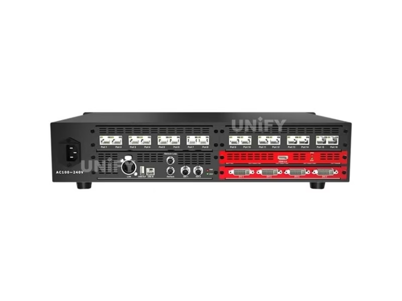
The sending layer, in a five-step capacity ladder — 1.3M → 2.3M → 5.24M → 8.88M → 13.1M pixels. Each step doubles the port count and adds a processing layer: multi-window scaling from the X8m, Genlock from the X16, HDR and 10G fiber from the Z6 PRO-G2.
Category 2 of 3
Colorlight LED Controller Series: I-Series Receiving Cards
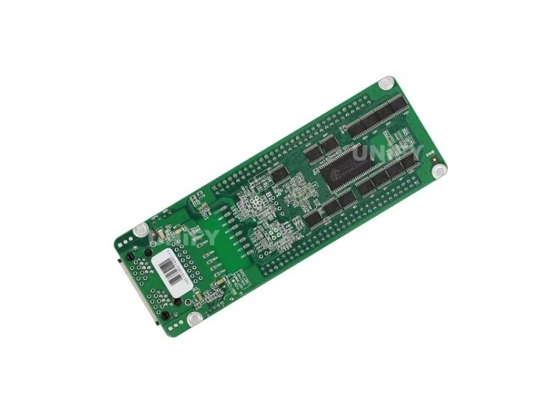
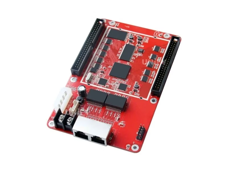
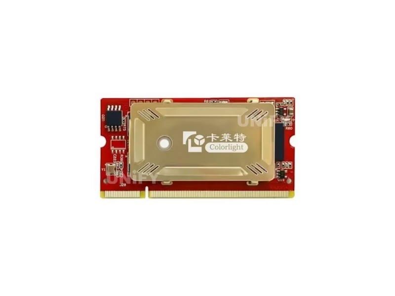
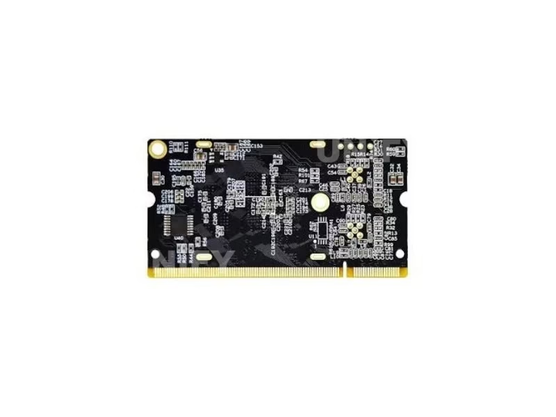
The cards inside every cabinet — current-generation SODIMM modules on a DDR2 200-pin socket, not the pin-header cards older guides describe. Selection runs on two numbers: data group count (16 → 32 → 64) and pixel loading.

Category 3 of 3
Colorlight LED Controller Selection Guides & Quick Reference
Five in-depth engineering guides, plus a quick-reference table for the most common project profiles:
Quick Reference: Match Your Project to a Model
Resources & Support
Colorlight LED Controller Resources & Support
Twelve engineering articles, the LEDVISION software ecosystem and factory support in one place.
Configuration & Debugging
Redundancy & Backup
Fundamentals
Engineering & Maintenance
Configuration Essentials
Every product on this page configures through the same ecosystem: LEDVISION for playback control and scheduling, LEDSetting for screen configuration, LEDUpgrade for firmware. The workflow in one line: wire the chain with a direct Gigabit connection, open LEDSetting with password 168, load the module supplier’s .rcfg file (the wrong .rcfg — or one from another brand — is the number-one cause of garbled images), set data groups, draw the mapping, then send and save. The full five-step routine, calibration coefficient maintenance and redundant firmware practice are in the LEDVISION setup guide. Two official tutorials cover the essentials:
Colorlight Official — LEDVision EP07 Configuration and Mapping tutorial
Colorlight Official — LEDVision EP09 How to Maintain Calibration Coefficients tutorial
FAQ
Colorlight LED Controller FAQ
Colorlight LED Controller Certifications
Every batch ships with Colorlight original packaging and full compliance documentation.
Ready to Source Colorlight LED Controllers?
Complete control systems, factory-direct pricing, .rcfg and LEDVISION support.
unifyledscreen@gmail.com | +86-191-18802497
Technical Deep-Dive
Colorlight LED Controller System Explained: Architecture, Models & Selection
Published: August 2026 | 12 min read | UnifyLED Engineering Team
Colorlight’s control system looks complicated from the outside — an X series with ten-plus model suffixes, a Z series, an I series of receiving cards, three software tools, and spec sheets that disagree with each other across versions. From the inside it is one pipeline with a small number of decision points. This guide walks the pipeline end to end: what each hardware layer does, how the capacity ladder works, how the receiving card math runs, and where the configuration, reliability and procurement practices fit. It is the article to read before the catalog above, or after it, when the catalog raises more questions than it answers.
Chapter 1 — The Pipeline: One Chain, Five Layers
Every synchronous Colorlight system moves pixels through the same five layers. Layer one is the video source — a media server, camera or computer — feeding the controller. Layer two is the sending controller: an X-series box or Z-series super controller that receives the signal, scales and processes it, and divides the frame across its output ports. Layer three is the transport: Gigabit Ethernet carrying up to 655,360 pixels per port on the X series, or 10G optical fiber on the Z6 PRO-G2. Layer four is the receiving card inside each cabinet — the I series — which buffers its portion of the frame and clocks it out to the modules. Layer five is the module itself, with its driver ICs lighting the LEDs. The design work on any project is deciding what belongs in each layer; the model families exist to make those decisions concrete.
The architectural split that matters most is synchronous versus asynchronous. Synchronous systems — everything in the X, Z and I-series families — need a live video source and render it in real time. Asynchronous players store content on the box and loop it without any source. Many walls run both: a player looping branded content during business hours, with a synchronous controller taking over for live events. See synchronous vs asynchronous LED control for the full comparison.
Chapter 2 — The Sending Layer: The X vs Z Split
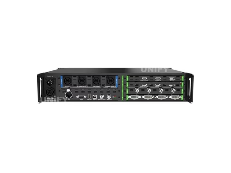
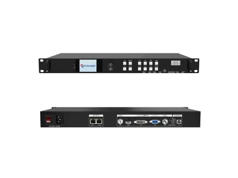
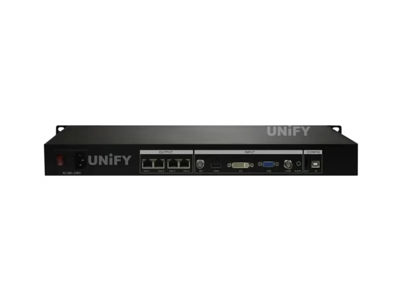
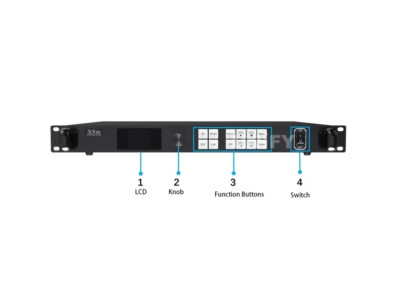
The X series is a capacity ladder, and the capacity numbers are the first thing to verify against official documents, because marketplace listings repeatedly misstate them. The verified ladder: the X2 loads 1.3M pixels over 2 Gigabit ports with 5 inputs — listings claiming four RJ45 ports or 4096-pixel capacity are describing a different box. The X4 loads 2.3M over 4 ports with a 4096×2560 canvas — the 2.6M figure belongs to the X4m variant. The X8m loads 5.24M at 60Hz over 8 ports with six independent windows and Genlock, and its “Ultra-4K” marketing means a 4K60 input mapped onto the 5.24M canvas, not 8.85M of output. The X16 loads 8.88M over 16 ports with seven windows, Genlock IN plus loop-out — and no DisplayPort input, despite listings that mention one. Each page linked here documents the correction against the official specification.
The Z6 PRO-G2 is the other species. It moves transport from copper to 4×10G optical fiber, carries HDR10 and HLG, a hardware 3D-LUT for color grading, and Frame Multiplexing that pairs fiber ports for virtual production. Its official specification states two capacity figures — 8.80M in the overview and 13.10M in the hardware section — which is a documentation inconsistency we verified against the spec, not a typo in this article; the practical ceiling depends on the fiber module configuration, and both figures ship in the official document. The selection rule: fixed installations with one source and a copper run choose the X ladder; broadcast, HDR and long-fiber runs choose the Z.
The full ladder with the correction notes is in the X series selection guide, and the brand-level comparison in Colorlight vs Novastar.
Chapter 3 — The Receiving Layer: Six Cards, One Math
The I-series catalog spans six cards on one generation: the i5A-905 (16 data groups, 256×256 loading, 16,000Hz refresh ceiling), the i5A-F (dual-mode with 2Gbit fallback memory — the wall keeps displaying through a primary firmware or memory failure), the i6 (32 groups, 3D, low latency, redundant firmware), the i9 (HDR10 and HLG, 120–240Hz), and the i9+ flagship (256×1024, SHUTTERLOCK, 3D). One framework correction: older guides describe receiving cards by HUB port counts, because that was the 5A-era architecture. The current cards plug into a DDR2 SODIMM 200-pin socket on the HUB board — a tool-free module format, not a pin-header card.
The selection math uses two numbers. Data group count — 16, 32 or 64 serial — sets how many module inputs one card can drive, and each group carries up to 8,192 pixels. Pixel loading sets the theoretical ceiling: 256×256 for the compact cards, 384×256 for the i9, 256×1024 for the i9+. On module-dense walls the groups bind first: a wall of 128×64 modules in a 32-group layout takes one card per two modules, which usually beats the loading limit. The complete method, with the scan-mode conditions: Colorlight receiving card selection guide.
Chapter 4 — The Software Layer: LEDVISION, LEDSetting, LEDUpgrade
One software ecosystem covers every product on this page. LEDVISION is the playback control tool — program-page-window structure, scheduling, real-time control. LEDSetting is the configuration tool that ships with current versions: screen settings, receiver parameters, mapping, calibration data. LEDUpgrade handles firmware. The version split follows the hardware: older S2 and S4 sending cards run LEDVISION V5.0–V7.0; the current X and Z series need V8.0 or later, which is also where the calibration coefficient backup and receiver parameter backup functions appear.
The .rcfg file deserves its own paragraph, because it is the single most common source of field failure: it encodes the module’s driver IC type, scan mode and data routing, it is module-specific, and a Colorlight card will not accept a Novastar .rcfg. The configuration sequence that surrounds it — detect devices over a direct Gigabit connection (password 168), load the .rcfg or run Intelligent Setting, set data groups, draw the receiver mapping from the front view, then send and save — is documented step by step in the LEDVISION setup guide.
Calibration completes the software layer. Per-pixel brightness and chroma coefficients live in each receiving card, and since V8.8 LEDVISION carries a dedicated backup function for them — readback, export, re-import after a card swap. Seam correction coefficients carry position data and must return to the same seam position. The maintenance routine, demonstrated officially:
Colorlight Official — 02 Data Group Swap and Split in LEDSetting tutorial
Chapter 5 — Selection in Practice: Three Project Profiles
Profile one: a fixed retail wall, 6m×3m P2.5, single media server source. The pixel count is 2400×1200 = 2.88M — past the X4’s 2.3M, so the controller is an X8m (5.24M headroom, six windows for the split layouts) or two cascaded X4s; the receiving cards follow the module count — with 128×64 modules the wall needs roughly 250 modules, meaning about 125 cards at 16 groups or 63 at 32 groups. The economical answer is one X8m and 32-group i6 cards, with a 5% spare ratio.
Profile two: a rental stage wall with camera feeds. The content plan includes live cameras and fast load-in/load-out, so the controller is an X16 (16 ports, Genlock for the camera sync, seven windows for the layer work) and the cards are i9s for the HDR camera signal — with the i5A-F as the fallback choice where a blackout is unacceptable mid-show. Profile three: a broadcast or virtual production canvas above 8M pixels — the Z6 PRO-G2’s 10G fiber ports remove the copper run limits, HDR10/HLG covers the camera chain, and i9+ cards hold the 256×1024 canvas with SHUTTERLOCK for the camera shutter sync. Each profile is the same pipeline with different layer decisions, which is the point of the catalog: the architecture is constant, the choices are finite, and the math is public.
Spare planning wraps the selection. The field-tested ratio is 5% of card count with a minimum of two — a 40-card wall holds two spares — and rental fleets that standardize on one card platform carry one spare population instead of three. The same discipline applies to controllers: a fixed-installation project with a single X4 carries one spare unit or a documented swap path. Spares are the cheapest insurance in the control system, and the most commonly skipped line item on the order.
Chapter 6 — Reliability: Redundancy and the Mixed-Generation Rule
Colorlight’s reliability features are consistent across the catalog: loop redundancy keeps screens displaying through cable faults, dual-bank firmware prevents bricked updates, configuration parameter redundancy allows instant restore, and calibration coefficient redundancy preserves a card’s exact correction state through replacement. The system-level view is in LED display system redundancy backup and multi sending card backup cascade.
One rule spans every family: keep firmware, configuration and coefficients together as one bundle. Firmware updates run through LEDUpgrade with the redundant bank verified afterward; configuration files come from the LEDVISION save-and-export steps; coefficients from the V8.8 backup routine. When a card fails and a replacement goes in, the three restore in sequence — parameters and mapping first, coefficients second — and the wall returns to its calibrated state within minutes. The maintenance cadence that surrounds the rule — quarterly audits, white and grey frame checks, spare ratios — is covered in LED screen maintenance.
Chapter 7 — Procurement: Verified Figures and the 2026 Price Reality
A control system order spans three product families, which multiplies the value of one disciplined channel. One supplier that provides controllers, cards and the matching .rcfg files together delivers three things a mixed basket of marketplace purchases cannot: configuration files matched to your actual module models, serial-number records across the whole system, and one support contact when the wall is down. Genuine verification follows the same checks on every product — original packaging, silk screen quality, and the specification version stated on the datasheet. Every Colorlight specification carries a change-history table; a supplier that can state the version in one sentence is behaving like an authorized channel.
Pricing discipline matches. Our verified prices 2026 article lists the full ladder with the bands we could verify against factory quotes — and states plainly where public prices do not exist, because controllers in this industry are factory-quote items, not list-priced ones. The 2026 context matters: module and driver-IC supply shifts through 2026 have moved controller pricing more than most buyers expect, and a catalog that quotes 2024 numbers is describing a market that no longer exists. Warranty and longevity follow the family standard: solid-state designs, low power draws, passive cooling — failures are dominated by defects and installation damage, not wear. A 2-year warranty with LEDVISION support is the practical baseline across the catalog.
For the full-system view — power budgets, installation and lifespan — LED display power consumption, LED screen installation and LED screen lifespan cover the layers beyond the control system.
Shopping Else? Open the Other Controller Catalogs
LED screen display control system — the six-brand master catalog