
Multi-Sending Card Backup and Cascading for Mission-Critical LED Walls
When an LED display exceeds a single sending card’s capacity—or when the application demands that no single card failure can take the display offline—multiple sending cards work together in cascade. Multi-sending card backup and cascading is the architecture that powers large-format LED walls: stadium displays, broadcast studio backgrounds, control room video walls, and any installation where pixel counts exceed a few million or where uptime is non-negotiable.
As a LED screen manufacturer, we design multi-card systems for large-format and mission-critical installations. For the single-card context, see our guides to system redundancy and port backup configuration.
Why Do LED Walls Need Multi Sending Card Backup and Cascade Setup?
Three reasons drive a multi-card architecture. First, pixel count exceeds single-card capacity—a 4K display contains 8.3 million pixels; a standard 4-output sending card drives approximately 2.6 million. Second, independent content zones—different sections of the display require different video sources, each feeding a dedicated card. Third, redundancy—a spare card in N+1 configuration can assume the load of any failed card, maintaining full display operation through a component failure.
How to Configure Multi Sending Card Cascade for LED Video Walls?
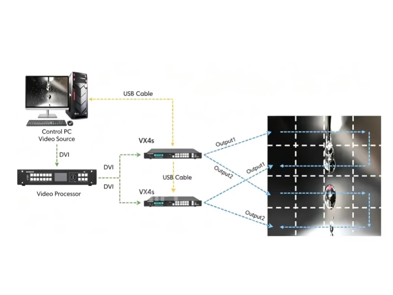
Multiple sending cards are connected via a cascade synchronization cable—a dedicated physical connection that ensures all cards operate in frame-level lockstep. One card is designated as the master; all others are slaves synchronized to the master’s timing. Without this cable, each card runs on its own internal clock. Even if all are nominally set to 60Hz, their clocks will drift apart, producing visible image tearing at the boundaries between cards—because adjacent cabinets driven by different cards are showing different frames at the same moment.
In Nova LCT, configure the cascade by designating one card as “Master” and connecting additional cards as “Slaves” via the sync ports. Each card is assigned a defined region of the total display canvas. The master’s video input—or a video processor feeding all cards through a distribution amplifier—provides the source. For 4K and larger installations, a video processor with multiple synchronized outputs typically feeds all cards, with the processor handling the signal splitting and the cascade sync cable maintaining frame lock between cards.
What Is N+1 Redundancy in Multi Sending Card Backup for LED Walls?
In an N+1 configuration, the system has one more sending card than required to drive the display—N cards for normal operation, plus 1 spare. If any of the N active cards fails, the spare card assumes its output mapping and takes over that section of the display. The switchover requires: identical configuration on the spare card matching all active cards, video signal feeding the spare card’s input, and control software configured to detect a card failure and initiate the switchover. The switchover time is typically 1–3 seconds.
N+1 redundancy costs one additional sending card—a small fraction of the total display investment for the protection it provides. For installations where a single sending card failure would take a significant portion of the display offline and the downtime cost exceeds the hardware cost many times over, N+1 is the standard engineering approach.
FAQ: Multi Sending Card Backup and Cascade for LED Wall Systems
Strongly recommended. Different models may have different processing latencies, firmware versions, or feature sets that complicate cascade synchronization. Using identical cards ensures identical behavior. If different models must be used, verify cascade compatibility with the manufacturer before purchasing.
Without a redundant master configuration, all slave cards lose their timing reference and the display will exhibit visible artifacts within seconds. For the highest level of protection, configure the cascade with a backup master—a designated slave card that can assume master timing duties if the primary master fails. This requires cards that support master redundancy.
Why Multi Sending Card Backup and Cascade Is Critical for Mission-Critical LED Walls
Multi-sending card cascade and backup is the architecture that scales LED displays beyond the limits of a single controller. The cascade sync cable is not optional—it is what keeps multi-million-pixel displays showing one coherent image instead of a patchwork of frame-mismatched sections. N+1 redundancy is not excessive—it is what keeps a broadcast studio on air when a sending card fails during a live production. Design the cascade during system planning. Test failover during commissioning. Document the configuration for the next technician.
Email: legidatechled@gmail.com | WhatsApp: +86-191-18802497