
Mooncell LED Controller Troubleshooting: Complete 2026 Guide
Mooncell LED controller troubleshooting follows a pattern that repeats across the whole family: read the LED, check the cable, read the configuration back, and replace with a card that inherits the settings. This guide walks the four failure classes — display faults, detection failures, flicker and black sections — with the official status-LED semantics for the A712, A10X, MTB sending controllers and the player boxes, and ends with the prevention discipline that keeps field failures rare in the first place.
Short answer: Most Mooncell LED controller problems are diagnosed in under ten minutes: a black section with the status LED off points to the network cable or sending port; a flickering section with the LED flashing normally points to the signal chain between sending and receiving cards; a card that AutoLED cannot detect points to USB, firmware or the network segment; and a color fault after a swap points to missing calibration, fixed by configuration readback. One semantic trap costs technicians the most time: on receiving cards a slow-flashing status LED means healthy, while on the MTB sending controllers a steady-flashing port LED means connected — the two families read in opposite directions.
What Are the Common Signs of a Mooncell LED Controller Problem?
Field failures arrive in four recognizable shapes, and each shape points to a different part of the chain:
The general troubleshooting sequence — wiring, network mapping, module configuration, correction — is documented step by step in the LED display configuration and system debugging guide; this page specializes it for Mooncell hardware.
How Do You Diagnose a Mooncell Receiving Card by Its Status LED?
Both Mooncell receiving cards carry the same four-state status code, documented in the official sheets — the A10X (U9) and the A712 (U1):
A black section with a constant-off status LED is a cable or port fault, not a card fault — swap the network cable first, then the port, then the card. The full receiving-card field guidance is on the LED display signal cable troubleshooting and basic debugging of LED displays guides.
A practical note on reading the receiving-card LEDs in groups: on a large wall the fastest fault-location pass is a quick walk with a flashlight reading every visible status LED — a single constant-off LED isolates the cabinet, a run of three or four off LEDs toward the loop end isolates the cable segment between them, and a wall-wide pattern of off LEDs points back to the sending port. The same walk reads the power LEDs: the A712’s U3 and the A10X’s U8 stay red when power is present, so a dark power LED on one card while neighbors are lit is a power-rail fault in that cabinet, usually the connector or the supply tap rather than the card itself. Combine that pass with the serial-number detection in AutoLED and the fault is located before the first cable is touched.
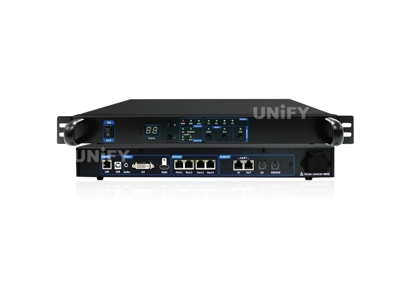
MTB400E front panel — P1–P4 LEDs flash when connected, stay on when not.
How Do You Read the Mooncell Sending Controller Front Panel?
The MTB400E and MTB2000E sending controllers read in the opposite direction from the receiving cards — the semantic trap that sends technicians hunting faults that do not exist:
On the MTB2000E the front panel adds an LCD 320×240 with a rotary knob and ESC — the same operating surface as the BS-Series B1200S — so a menu-level fault read happens without a laptop. When the panel says the controller is healthy but a wall section is dark, move downstream: the cable-quality and error-rate readings in AutoLED will say which receiving chain is failing.
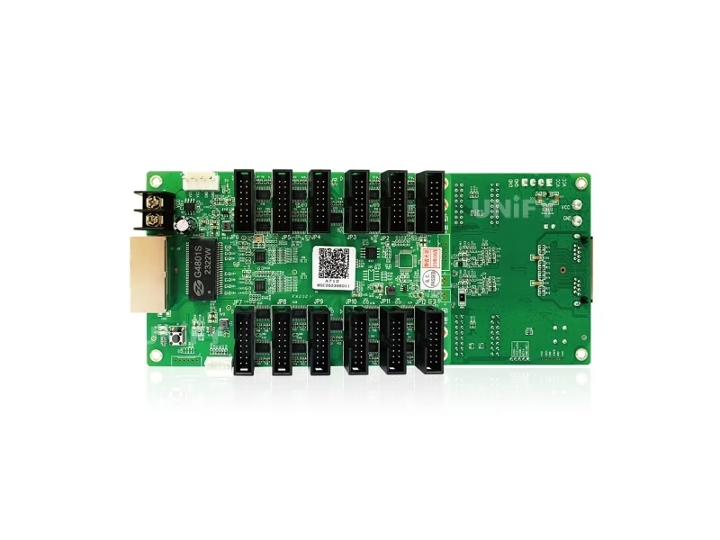
A712 status LED — four-state code on the card edge.
Why Can’t AutoLED Detect the Mooncell Sending or Receiving Card?
Detection failure is the most common first-hour question, and the fix follows a five-step ladder that clears most cases in minutes:
- Check the USB indicator. The MTB sending controllers and player boxes light a USB LED only when the control cable is properly seated — a dark USB LED means re-seat before anything else.
- Verify the driver and port. AutoLED connects through the Mooncell driver; a changed USB port or a driver update from the LED sending card configuration guide fixes the majority of “card not found” reports.
- Match firmware generations. A receiving card on older firmware may not enumerate under a newer AutoLED — run the online upgrade path first, then retry detection.
- Isolate the network segment. For receiving cards, detection runs through the sending stage’s network — test one card on the nearest port before suspecting the chain.
- Reset and retry. The player boxes carry a RESET switch that restores factory settings; the sending controllers use the front-panel menu. Reset only after the configuration is backed up via readback.
One detection case deserves its own paragraph because it is a configuration trap, not a hardware fault: the MTB400E carries a digital brightness display and the A712 family exposes power-status detection as a customization — if a wall runs dark but every LED reads healthy, verify the brightness policy (manual, scheduled or light-sensor) before touching cables. The sending tiers accept input frame rates of 30/50/60/120 Hz and preset resolutions from 1024×768 to 2560×960; a source outputting outside the configured set can present as “no signal” on the input LED while the wall hardware is fine. Set the source to the wall’s EDID expectation first — the synchronous playback troubleshooting guide covers the mode side of the same class of fault.
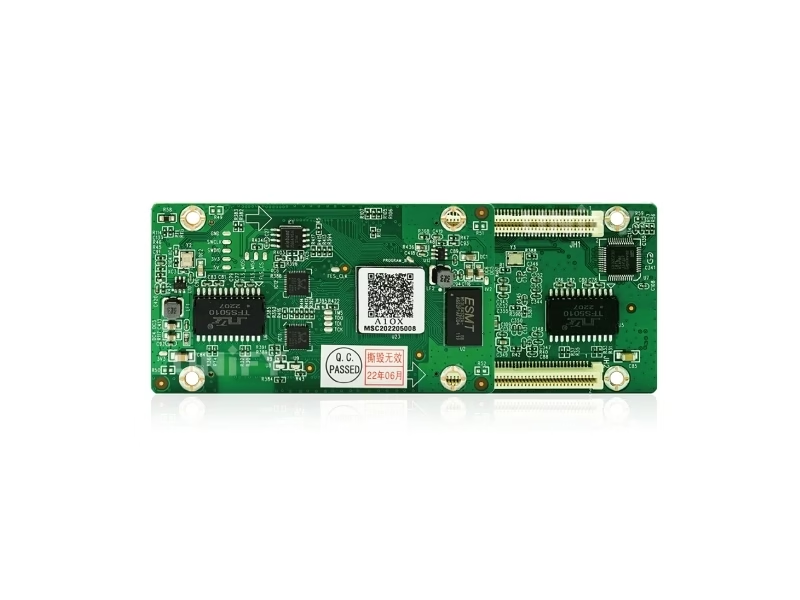
A10X receiving card — the component the signal chain feeds.
How Do You Fix a Flickering or Black Section on a Mooncell Wall?
Flicker and black sections live in the same place: the signal chain between the sending stage and the receiving cards. The diagnostic order is:
- Read the cable quality in AutoLED. The sending controllers and the A10X/A712 family report Gigabit error rates and cable signal quality in real time — a marginal cable is flagged before it becomes an intermittent black section.
- Follow the loop topology. If the section’s card shows the three-interval-flash state, the loop is active and the fault is upstream — check the sending port and the previous card in the chain.
- Test with the inspection key. The MTB400E’s INC key runs an inspection pass; a card that passes inspection but shows dark content is a configuration issue, not a hardware one.
- Swap in the spare card. At one spare per ten installed, the field swap is the fastest proof — and because the card inherits configuration via readback, the swap is minutes, not a re-commission.
Flicker at the whole-wall level, by contrast, is almost never the receiving tier — check the source frame rate against the controller’s input range (30/50/60/120 Hz on the sending tiers) and the camera-shutter interaction, covered in the LED screen flickering guide. Uneven brightness across sections points to calibration, not hardware — the uneven brightness troubleshooting guide walks the correction path.
A section-level fault that survives a card swap points to the module or its wiring, and the Mooncell diagnostic path has two tools for it. First, the network-port debugging in AutoLED shows the card serial number and its connection line on the target box — the fastest way to confirm a section is wired to the port the configuration expects. Second, the Seam Tool on the A712 family and the pixel-level calibration on the A10X adjust brightness and chromaticity per pixel, so a section that looks off after a swap usually needs its correction data restored from the readback file rather than a new calibration run. When the fault moves with the module, the LED display troubleshooting guide and the dead pixel and module replacement guide take over from the controller side.
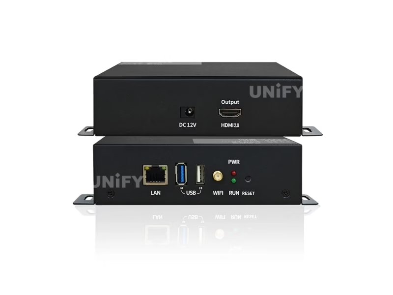
MB401 — PWR steady green, Run flashing when the OS is healthy.
How Do You Troubleshoot Mooncell Player and Creative Controller Issues?
The player boxes and creative controllers bring their own indicator sets. The MB401 and MP-series players carry two LEDs: PWR steady green confirms power, and the Run LED flashing means the Android OS is alive — a steady-on or steady-off Run LED points to an OS fault before any cable is touched, and the Reset switch restores factory settings (back up programs first through the cloud or USB). The MB400S creative player adds 4G and Wi-Fi hotspot indicators to the PWR/RUN pair, so a network fault on a remote creative wall is read at the front panel without a phone call. The B1200S and the V Series splicer are project-tier hardware: field faults route through the integrator and Mooncell’s official support line (400-881-3531), and the configuration readback and auto-recovery paths on both families mean a swapped unit inherits the wall’s state.
The player and creative tiers have their own three checks. On the MB401, a content fault that survives a reboot is usually a program issue, not hardware: re-deploy through the cloud cluster or USB plug-and-play, and confirm the Android 11 platform has not silently reverted to a previous program state. On the MB400S, a remote wall that reports offline needs the 4G/Wi-Fi indicators read at the panel before dispatching — the antenna seating is the most common false-offline cause. On the MC-C2 server tier, keep the broadcast software version matched across the fleet — the playlists and schedules guide covers the content side of the same discipline.
How Do You Prevent Mooncell Controller Failures on Site?
Prevention is a five-item discipline that costs less than one night call:
One receiving card per ten installed, ordered in the same firmware batch — a swap inside the batch never introduces a firmware mismatch.
Save the configuration readback after commissioning — the replacement path and the rollback path both start from that file.
Run loop backup where the wall cannot blink — the three-interval-flash state confirms the loop is live.
Dual power inputs on the A712 family and redundant 550 W modules on the MTB2000E/V500+ — a PSU failure stops being a wall event.
The LED display system redundancy & backup guide covers the full picture, and the LED display troubleshooting guide links every deeper fault class.
Firmware discipline rounds out prevention: both receiving-card families and the sending controllers upgrade online through AutoLED, and the FPGA dual-program startup on the receiving cards means an interrupted upgrade boots a standby program instead of a dead card — but the upgrade window should still be a scheduled one. Keep the fleet on one firmware revision per site, keep the older revision’s upgrade files on file for rollback, and run the upgrade during a maintenance window with the readback file already saved. The same discipline applies to the MTB sending controllers and the players, whose online updates pull from the Mooncell cloud resources — a fleet at mixed revisions is the silent cause of “it worked yesterday” reports.
What Do Buyers Ask About Mooncell LED Controller Troubleshooting?
Two deeper fault families are worth naming so the right guide is at hand when they appear. White or bright spots in a section point to module or driver faults on the panel side, not the controller — the white spots fix guide covers them. Content that plays wrong on an async wall — wrong schedule, wrong program, no update — is a player-management issue that the asynchronous playback troubleshooting and cloud content updates guides resolve. Every link in this page sits in the wider LED display troubleshooting matrix, so a Mooncell fault is never more than one hop from a documented fix.
Conclusion: How Do You Keep a Mooncell Controller Fault Short?
Mooncell LED controller troubleshooting is a repeatable sequence because the hardware is consistent: read the status LED against the official semantics, work the detection ladder when software goes blind, follow the signal chain for flicker and black sections, and keep the readback file and same-batch spare that make every fix a swap instead of a re-commission. The two families read in opposite directions — receiving cards flash slowly when healthy, sending controllers flash steadily when connected — and remembering that one inversion saves most of the night calls. Every indicator code in this guide is quoted from the official V4.x sheets on the A712, A10X, MTB400E, MTB2000E and MB401 pages, and the deeper fault classes link outward to the full troubleshooting matrix. A wall that knows its LEDs is a wall that comes back quickly.
Running Mooncell hardware and want a faster fix path? Talk to us — we are the LED screen manufacturer behind unifyled.com, and every system we ship comes with our engineering support on the AutoLED configuration.