
What Is LED Anode Cathode? How to Identify, Test & Wire It
Every LED — from a 2 mm indicator lamp to the SMD2121 lamp beads on a 4K video wall — has two electrical terminals: the anode and the cathode. Confusing the two is one of the most common causes of a lamp bead that will not light, a module that shows dark dots, or a repair that fails twice. This guide comes from the production floor of an LED screen manufacturer and explains what LED anode cathode terminals are, how to identify each one on through-hole and SMD packages, how to test them with a multimeter, and how the anode cathode structure shapes the way an LED display module is driven and repaired.
Short answer: LED anode cathode describes the two terminals of a light-emitting diode. The anode is the positive terminal that current enters, and the cathode is the negative terminal that current leaves. An LED only emits light when the anode is connected toward the positive side and the cathode toward the negative side. On through-hole LEDs the long leg and the flat edge mark the polarity; on SMD lamp beads you read the package marking; with a multimeter set to diode mode, the bead glows faintly when the red probe lands on the anode. Reversed briefly, an LED simply stays dark; reversed beyond its reverse voltage rating for long, it breaks down and dies.
1. What Are the Anode and Cathode of an LED?
An LED anode cathode pair is the two electrical terminals of a light-emitting diode. Anode is the positive terminal — current flows into the diode through it. Cathode is the negative terminal — current flows out through it. In circuit diagrams the LED symbol is a triangle pointing at a bar: the triangle (arrow) side is the anode, the bar is the cathode, and the two small arrows leaving the symbol represent the emitted light.
LED stands for light-emitting diode, and the word “diode” carries the whole rule: a diode conducts in one direction only. Apply forward voltage — positive at the anode, negative at the cathode — and the PN junction conducts, electrons recombine, and the chip emits light of a fixed wavelength. Apply the voltage the other way around and the junction blocks; no current, no light. The emitting chip inside a lamp bead is smaller than a grain of salt, and its two bond pads are exactly anode and cathode.
On an LED display, this structure repeats thousands of times. Each pixel in a full-color module packs red, green, and blue chips inside one SMD package, and every chip keeps its own anode and cathode bonded to the package frame. When you hear that a display has 250,000 pixels per square meter, you are also hearing that more than 750,000 anode cathode junctions are switching on and off thousands of times per second — which is why polarity discipline matters at every stage from PCB design to lamp bead replacement.
2. Why Do LEDs Have Polarity?
LEDs have polarity because the light-emitting junction is a PN diode, not a resistor. In forward bias — anode positive relative to cathode — the depletion layer at the PN junction narrows above the threshold voltage and current crosses the junction freely. In reverse bias the depletion layer widens and blocks current, the same way a check valve blocks backflow.
The reverse side has a limit. Standard indicator and display LEDs carry a reverse voltage rating of about 5 V in mainstream manufacturer datasheets (Lumileds, Cree LED, and OSRAM datasheets list VR = 5 V for most standard families), and exceeding it forces the junction into reverse breakdown. A brief excursion within the rating does nothing; a sustained over-voltage drives uncontrolled reverse current through a junction that was never designed to dissipate it, and the chip dies.
For display engineering this rule sits one level higher: the driver IC does not touch the AC mains — it switches low-voltage constant-current channels against the lamp beads’ anode cathode structure. What the PCB must get right is which pad carries the anode rail and which pad carries the cathode channel of the driver. That mapping is fixed in copper on the module PCB, which is why a correctly designed module never leaves the factory with a polarity problem — but a hand-replaced lamp bead can reintroduce one.
3. Which Leg of an LED Is Positive — Anode or Cathode?
On a through-hole LED the longer leg is the anode (positive) and the shorter leg is the cathode (negative). Three physical clues let you confirm LED anode cathode polarity by eye, even when both legs are trimmed to the same length:
- Lead length: the longer lead is the anode; the shorter lead is the cathode.
- Flat edge on the rim: the plastic flange at the base has a flattened section on the cathode side.
- Internal metal size: looking into the epoxy, the larger metal piece — the cup-shaped reflector that holds the emitting chip — connects to the cathode; the smaller post connects to the anode.
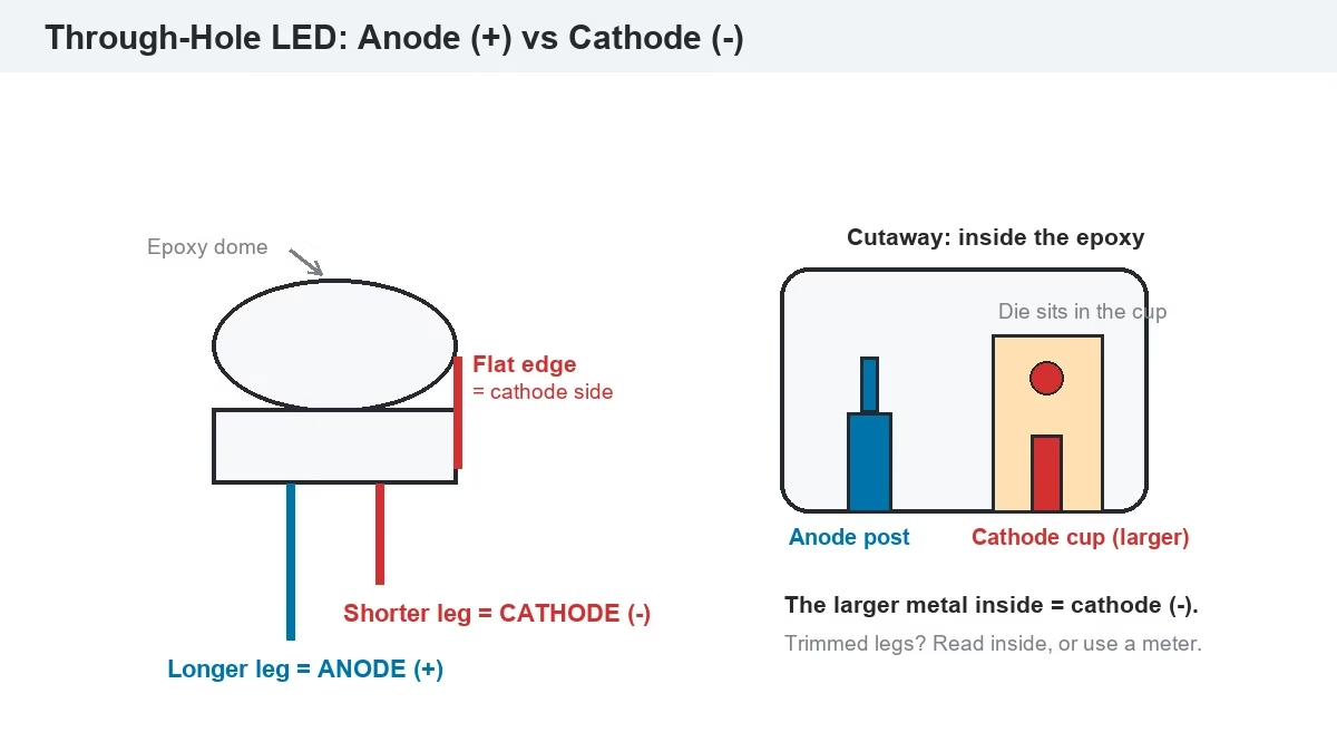
The third clue is the reliable one once leads are cut. The emitting die sits inside the reflector cup on the cathode side, so the cup looks visibly larger than the anode post. If the view is unclear, skip the guessing: a 3-second diode-mode test (Section 5) settles it.
| Clue | Anode (+) | Cathode (−) |
| Lead length | Longer leg | Shorter leg |
| Rim flange | Round side | Flat edge |
| Metal inside the epoxy | Smaller post | Larger reflector cup |
| Circuit symbol | Triangle (arrow) side | Bar the arrow points to |
4. How to Identify SMD LED Anode Cathode on a Display Module?
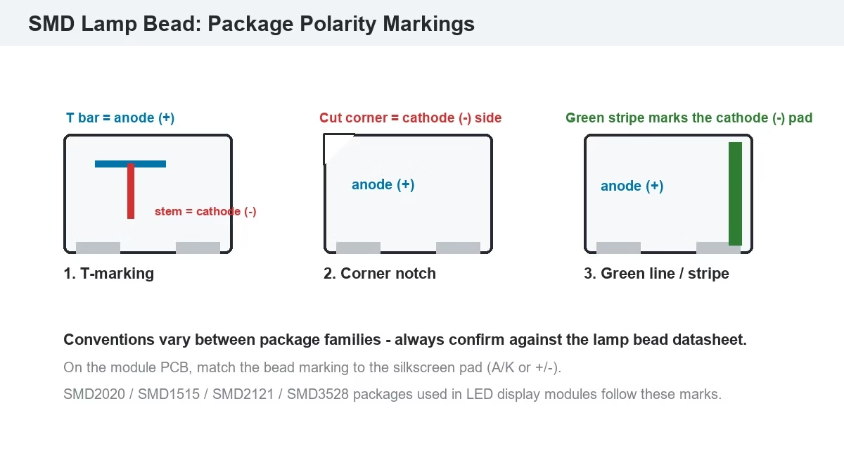
SMD lamp beads — the SMD2020, SMD1515, SMD2121, and SMD3528 packages used across LED display modules — have no legs to compare, so manufacturers mark the polarity on the package body instead. The markings follow a few conventions, and the module PCB repeats them in copper:
- T-shaped marking: the top bar of the “T” marks the anode (+) pad, and the vertical stem points at the cathode (−) pad.
- Corner notch or beveled corner: the cut corner sits on the cathode side of the package.
- Green line, dot, or stripe: a colored mark near one pad identifies the cathode on many package families.
- PCB silkscreen: module pads are labeled A/K or +/− in the solder-mask print, and the pad connecting to the driver IC’s current channel is the cathode side.
Because marking conventions vary between package families, the datasheet of the exact lamp bead model is the deciding reference — the first document any display factory checks before a rework line touches the module. This is also the layer where packaging choice interacts with polarity: an SMD bead exposes its two electrodes to the same air as the emitting chip, while COB and GOB packaging technologies seal the junction under resin, and the SMD vs COB vs GOB comparison explains what that changes for protection and repair.
5. How to Test LED Anode Cathode with a Multimeter?
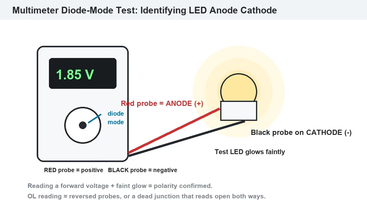
A digital multimeter in diode mode identifies LED anode cathode polarity and tests the junction at the same time. The meter applies a small fixed voltage between the probes — the red probe carries positive, the black probe negative — and displays the forward voltage it reads:
- Set the dial to the diode symbol (▶|).
- Touch the red probe to one lead and the black probe to the other.
- If the bead glows faintly and the meter shows a forward voltage, the red probe is on the anode and the black probe is on the cathode.
- If the display shows OL (open loop) and the bead stays dark, swap probes — that reading means you had the LED reversed.
The forward voltage reading also tells you the chip color: red chips drop about 1.8–2.2 V, yellow close to 2.0–2.2 V, and green and blue chips drop about 2.9–3.4 V (typical ranges from standard LED datasheets). A dead junction reads OL in both directions; a shorted one reads near 0 V in both directions.
Two field notes for display work. First, some meters supply less than a blue or white chip needs to visibly glow — a dark reading on a bead you suspect is fine may just be a weak test supply, so confirm on a known-good bead of the same model. Second, on a mounted module the faster diagnostic path is the receiving card’s lamp-point test (a single-color full-screen flash), which maps every anode cathode junction’s response pixel by pixel and is covered in the basic debugging guide for LED displays.
6. What Happens If You Connect LED Anode Cathode Backwards?
Connect an LED backwards and it simply does not light — no current crosses a reverse-biased PN junction. What happens next depends on how far the reverse voltage goes:
- Reverse voltage below the rating (≈5 V for standard LEDs): the junction blocks, the LED stays dark, and nothing is damaged. Swap the polarity and the LED works as new.
- Reverse voltage above the rating, held for time: the junction enters reverse breakdown, reverse current flows, the die overheats locally, and the LED fails permanently — usually as a dark or blackened spot.
Inside an LED display module the same failure shows up as a single dead pixel or an entire row that stays dark. A whole row or column going dark together is rarely lamp beads all failing at once — it points one level up, to the connector seated the wrong way, a ribbon cable reversed, or a power feed with reversed polarity, and the power supply diagnostics guide covers that class of fault. Burned individual beads that turned dark belong to the cases in the black spots on LED screen guide.
One boundary matters more than any other: reversed lamp-bead polarity and reversed power-supply polarity are different severities. A bead on the wrong way round is a single-point nuisance; a switching supply fed backwards can destroy the driver ICs across the module before anything visibly fails. Power wiring gets checked before lamp beads, every time.
7. How Do Common Anode and Common Cathode LED Displays Wire Polarity?
The anode cathode structure of each chip is also the basis for the two power architectures a full-color display can use. In a common anode design, every pixel’s anodes tie to one shared positive rail — typically 5 V — and the driver IC switches each chip by pulling its cathode low. In a common cathode design, the cathodes share a common line and each color’s anode side receives its own precise supply voltage: roughly 2.8 V for red chips and 3.8 V for green and blue.
The shared-rail approach is simpler, but it forces every chip to accept the same voltage. A red chip that needs only ~2 V forward drops the remaining volts across its driver channel as heat, which is why common cathode designs cut module power consumption by roughly 30–50% and lower surface temperature by about 15–20 °C at equal brightness, as measured in common cathode LED display technology. The saved watts compound over a wall’s running hours — the arithmetic is worked through in the LED display power consumption guide.
| Aspect | Common Anode | Common Cathode |
| Shared terminal | Anode on one positive rail | Cathode on a common line |
| Supply per color | Single voltage for R/G/B | ≈2.8 V red, ≈3.8 V green/blue |
| Excess voltage | Dissipated as heat in the driver | Removed at the source |
| Module temperature | Higher at equal brightness | ≈15–20 °C lower |
| Power draw | Baseline | ≈30–50% lower |
For a buyer the takeaway is direct: both architectures obey the same anode cathode physics, but the common cathode arrangement spends fewer watts turning into heat inside the module, which slows the brightness decay that heat accelerates.
8. Why Does LED Anode Cathode Polarity Matter for Module Repair?
Every lamp bead replacement is a polarity decision made with a soldering iron in hand. The replacement bead must sit with its anode pad on the anode pad of the PCB and its cathode on the cathode — match the package marking to the silkscreen, not to a neighbor bead, because a rotated bead is invisible from the front until the module powers up with one dark dot.
The repair sequence that keeps polarity errors out:
- Confirm the fault with the lamp-point test or a multimeter in diode mode — replace the bead, not the trace.
- Match the replacement to the same package model and read its polarity marking against the datasheet.
- Lift the old bead with hot air or a dual-tip iron, clean the pads, and note which pad the marking pointed to before removal.
- Place the new bead so its marking matches the silkscreen, reflow, and verify with the lamp-point test before the module returns to the wall.
The full workflow runs in the dead pixel repair and module replacement guide, and the fault-finding tree that leads to a lamp bead swap — as opposed to a cable, card, or power fault — is laid out in the LED display troubleshooting guide. The video below shows the lamp bead replacement step on a real module:
For wall-mounted screens without rear access, module removal itself is a front-service operation — the front-maintenance sequences are part of routine LED screen maintenance, and they keep bead-level repairs from turning into cabinet-level work.
9. FAQs about LED Anode Cathode
Which leg of an LED is positive?
The longer leg is the anode and it is the positive terminal. If both legs are trimmed, the flat edge on the rim marks the cathode side, and the larger metal piece visible inside the epoxy is also the cathode.
How do you identify SMD LED polarity without legs?
Read the package marking: the top bar of a “T” mark is the anode and its stem points to the cathode; a corner notch or a green line/stripe usually marks the cathode side. Confirm against the lamp bead datasheet, because marking conventions differ between package families.
What happens if you connect an LED backwards?
The LED blocks current and stays dark. Brief reversal within the reverse voltage rating (about 5 V for standard LEDs) causes no damage; sustained reversal above the rating drives the junction into breakdown and destroys it.
How can you test LED polarity with a multimeter?
Set the meter to diode mode. Red probe on the anode and black probe on the cathode makes the bead glow faintly and shows a forward voltage of about 1.8–2.2 V for red chips and 2.9–3.4 V for green or blue. An OL reading means the probes are reversed or the junction is dead.
What is the difference between common anode and common cathode LED displays?
Common anode ties every chip’s anode to one shared positive rail and switches on the cathode side; common cathode ties the cathodes together and feeds each color its own precise voltage. Common cathode removes the excess-voltage heat of the shared rail and cuts power consumption by roughly 30–50%.
Does reversed polarity damage an LED display module?
A lamp bead soldered in rotated only leaves that pixel dark until it is re-soldered. A reversed ribbon or connector leaves a row or column dark. A power feed wired backwards is the severe case — it can destroy driver ICs module-wide — so power polarity is checked before anything else.
10. Summary: What LED Anode Cathode Means in Practice
LED anode cathode is the pair of terminals that decides whether a light-emitting diode conducts: anode positive, cathode negative, light out — reverse it and the junction blocks. Through-hole LEDs carry the polarity in lead length and the flat rim edge; SMD lamp beads carry it in package markings verified against the datasheet; a multimeter in diode mode settles any doubt in three seconds and reads the forward voltage of each color as a bonus. In LED display work the same rule scales from a single bead to the power architecture of the whole wall — common anode shares one rail, common cathode splits the supply per color and keeps the module cooler for less power. Whoever solders a bead back onto a module is making a polarity decision, and the marking-plus-silkscreen match is what keeps the repaired pixel lit for the next 100,000 hours.
References & Sourced From: LED Anode Cathode Coverage
- SparkFun Learn — Diode and LED Polarity
- JLCPCB — How to Identify SMD LED Polarity: Markings, Testing, and PCB Tips
- Switch Electronics — LED Polarity Basic Guide
- Lumileds / Cree LED / OSRAM standard LED datasheets — reverse voltage (VR) and forward voltage specifications