
How to Configure Colorlight LEDVISION: Sender, Receiving Card and Mapping
Published: August 2026 | 12 min read | UnifyLED Engineering Team
A wall that lights up but shows a scrambled image, a cabinet that stays black, colors that break into bands — most installers reach these moments within the first hour on site. The LED screen itself is rarely the problem; the configuration chain is. This colorlight ledvision setup guide walks the complete configuration sequence in Colorlight LEDSetting and LEDVISION: detecting the sender and receiving cards, loading the correct module parameters, matching data groups, drawing the receiver mapping, and saving the result so it survives a power cycle. It then covers the two maintenance jobs that decide whether the wall stays healthy after handover: calibration coefficient upkeep and redundant firmware handling. Field experience from an LED screen manufacturer‘s commissioning teams, verified against Colorlight’s official documentation.
Before starting, confirm you know the basic structure of the control chain — the common functions and operations of control system software and hardware guide covers the fundamentals this article builds on.
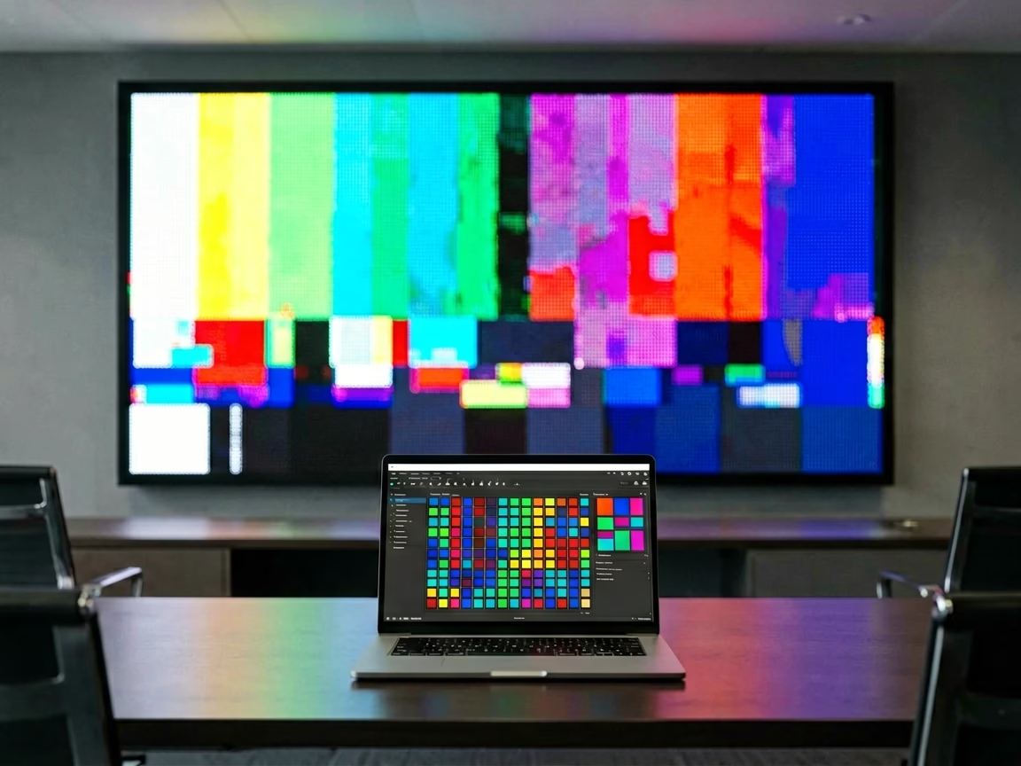
Short answer: Configure a Colorlight LEDVISION system in five steps — detect the sender and receiving cards over a direct Gigabit connection, load the correct .rcfg module parameters (or run Intelligent Setting when no file exists), match the data group layout to the module, draw and send the receiver mapping, then save to the receiving cards and export a backup. After handover, maintain the calibration coefficients with the V8.8+ backup function and keep the redundant firmware plus configuration backups in step — those two habits turn a failed card replacement from a half-day repair into a 10-minute swap.
- Quick fact — the five-step chain: detect → parameters → data groups → mapping → save. Every step in this order; skipping one breaks the next.
- Quick fact — the software split: LEDVISION handles playback, LEDSetting handles screen configuration. English tutorials rarely state this.
- Quick fact — passwords: 168 for screen settings, 777 on some devices.
- Quick fact — calibration: coefficients live in each receiving card; back them up before any card swap or firmware update.
What Is Colorlight LEDVISION and What Does the Setup Cover?
Colorlight LEDVISION is the control-and-playback software for Colorlight synchronous LED control systems: it builds the program-page-window content structure, schedules playback, and runs real-time control of the wall. Since the current software generation, the screen configuration work — screen settings, receiver parameters, mapping, calibration data — has been split into a companion parameter tool called LEDSetting. That split is the first thing to understand in any colorlight ledvision setup guide, because most English tutorials written for older versions describe every function inside LEDVISION and leave readers searching menus that no longer exist.
The version split follows the hardware. Sending cards from the older generation — the S2 and S4 — work best with LEDVISION V5.0 to V7.0. The current X-series and Z-series controllers call for V8.0 or later, which adds the calibration coefficient backup and receiver parameter backup functions discussed in Chapter 7. Install the wrong generation and the sending card either fails to appear in the device list or drops features on older firmware.
The configuration sequence itself is five steps:
- Detect devices — find the sending card and every receiving card on the network.
- Load receiver parameters — match the .rcfg file, driver IC and scan mode to the module.
- Set data groups — match the card’s data outputs with the module’s physical layout.
- Draw the mapping — tell the sender where each receiving card sits in the wall.
- Save and export — write the configuration to the cards and keep a local backup.
This sequence applies to synchronous playback walls. The synchronous vs asynchronous LED control article explains where the line runs — asynchronous players configure through their own web or USB interface, not through LEDSetting.
How Do You Detect the Sender and Receiving Cards in Colorlight LEDVISION?
Detection starts before the software opens. Connect the sending card directly to the PC’s Gigabit Ethernet port — no switch in between. Direct connection matters because LEDSetting’s detection probes the link layer; a managed switch can block or delay the broadcast, and the most common “card not detected” call from the field is solved by removing the switch from the chain. Use Cat5e or Cat6 cable, and confirm Windows reports the link at 1.0 Gbps.
The procedure in LEDSetting:
- Open Screen Configuration and enter the password — 168 by default, 777 on some devices.
- On the Sending Device tab, select the network card and click Detect to find the sender.
- Open the receiver detection page and detect on every Ethernet port — the software lists each receiving card found per port.
If detection still fails, check three things in order: the cable plugged into USB_IN instead of USB_OUT on USB-configuration cards, the PC’s IP subnet versus the card’s default range, and the network drivers. Only after all senders and receivers appear should you move to parameters — a partial device list produces a configuration that looks successful and fails on the wall. The Colorlight X2 LED video controller and Colorlight X4 LED video controller pages cover the two workhorse senders most walls start with.
Colorlight’s official walkthrough of the sender and video source setup:
Colorlight Official — LEDVision EP06 Sender and VideoSource Setting tutorial
Which Receiver Parameters Must Your LED Module Match in Colorlight LEDVISION?
A .rcfg file is the module’s configuration profile: it encodes the driver IC type, the scan mode, the data group count and the RGB channel order for one specific module design. Load a wrong .rcfg and the wall shows horizontal lines, wrong colors or a shifted image — the symptoms appear immediately, which makes parameter errors the fastest part of the setup chain to diagnose.
Two paths lead to correct parameters, and they are mutually exclusive in practice:
- Supplier file: when the module supplier provides the .rcfg, load it directly in the receiver parameters window and verify the driver IC and scan mode against the module datasheet. This is the reliable path for standard modules.
- Intelligent Setting: when no file exists — replacement modules from an unknown source, custom designs — run the wizard instead. It steps through the module’s lit rows, data groups, driver IC and scan mode by reading the physical module.
The scan mode is the parameter most often mismatched. A 1/16 scan module driven as 1/32 scan shows horizontal line bands; the reverse shows as a dim, washed-out image. The correction is the same in both directions: re-download the correct file from the module supplier or re-run the wizard. One boundary rule worth stating outright: Colorlight and NovaStar .rcfg files are not interchangeable — a file pulled from the other brand’s ecosystem will not configure the card correctly.
Three key differences between the two paths, in order of how often they cause field failures:
- File availability decides the path — with a supplier .rcfg, load it; without one, run Intelligent Setting. The wizard is the fallback, not the preference.
- Scan mode is the failure point — 1/8, 1/16, 1/32 mismatches are the most common cause of banding and washed-out color.
- Brand files do not mix — a NovaStar .rcfg on a Colorlight card produces garbage output, not an error message.
On the card side, the Colorlight i5A-905 LED receiving card, Colorlight i6 LED receiving card and Colorlight i9+ LED receiving card pages list the supported scan modes and data group counts for the current I-series line.
How Do Data Groups Work in a Colorlight LEDVISION Configuration?
A data group is one RGB data stream out of the receiving card, carried over the module’s flat cable, feeding a column of LED pixels. A standard indoor module might consume 4 to 16 data groups depending on its resolution and scan design; the receiving card’s job is to push the right stream onto the right physical connector. Colorlight’s current cards support up to 32 parallel RGB data groups, which sets the wall’s pixel ceiling per card — each group drives up to 8,192 pixels.
In the receiver parameters window, after loading the .rcfg:
- Set the data group count to match the module — the standard preset is 32 groups for full-size modules.
- Enter the module’s matrix width and height in pixels. If the software reports the size out of range, drop the refresh multiplier from ×16 to ×8; if still out of range, lower DCLK and re-check the refresh rate.
When the module’s physical connector order does not match the card’s default output order — common with custom and replacement modules — three tools fix the layout:
- Data group swap — reorders the card’s outputs to match the module’s input sequence.
- Data group split — divides one group across two or more module columns for high-density layouts.
- Data fold — cascades multiple module rows per group to raise the refresh ceiling on high-scan designs.
Colorlight’s official tutorial on data group swap and split:
Colorlight Official — 02 Data Group Swap and Split in LEDSetting tutorial
Group counts differ across the card line: the Colorlight i5A-F LED receiving card runs 16+20 groups in its dual-mode design, while the Colorlight i9 LED receiving card steps up to 64 serial groups for HDR-grade modules.
How Do You Map Receiving Cards in Colorlight LEDVISION?
Receiver mapping is the layout that tells the sending card where each receiving card physically sits in the wall — the installation sequence of the cards, port by port. Parameters make each cabinet show the right pixels; mapping makes the cabinets join into one coherent image. A wall with correct parameters and a wrong mapping shows recognizable content scattered across cabinets in the wrong order.
The mapping window works from the wall’s front view. The procedure:
- Select the sender port you are mapping.
- Set the row count and column count of receiving cards on that port — a 6×4 cabinet wall is 24 cards.
- Enter each card’s resolution in pixels — a card driving a 320×240 cabinet area takes 320×240.
- Draw the connection order: pick a connection pattern — standard, zigzag or U-shape — for regular layouts, or click card by card following the physical daisy-chain order for irregular layouts with cutouts or L-shapes.
Watch the per-port capacity readout while drawing. On X-series controllers the ceiling is 655,360 pixels per Gigabit port (1280×512) — when a port’s mapped area exceeds it, the software flags the port red. The reason is bandwidth, not software preference: each port’s pixel capacity is fixed by the controller’s hardware, so an over-capacity port cannot be configured away — redistribute the cabinets across ports instead. The Colorlight X8m LED video processor spreads this across 8 ports and the Colorlight X16 LED video controller across 16; the Colorlight Z6 PRO-G2 LED video controller removes the constraint almost entirely with 10G fiber ports.
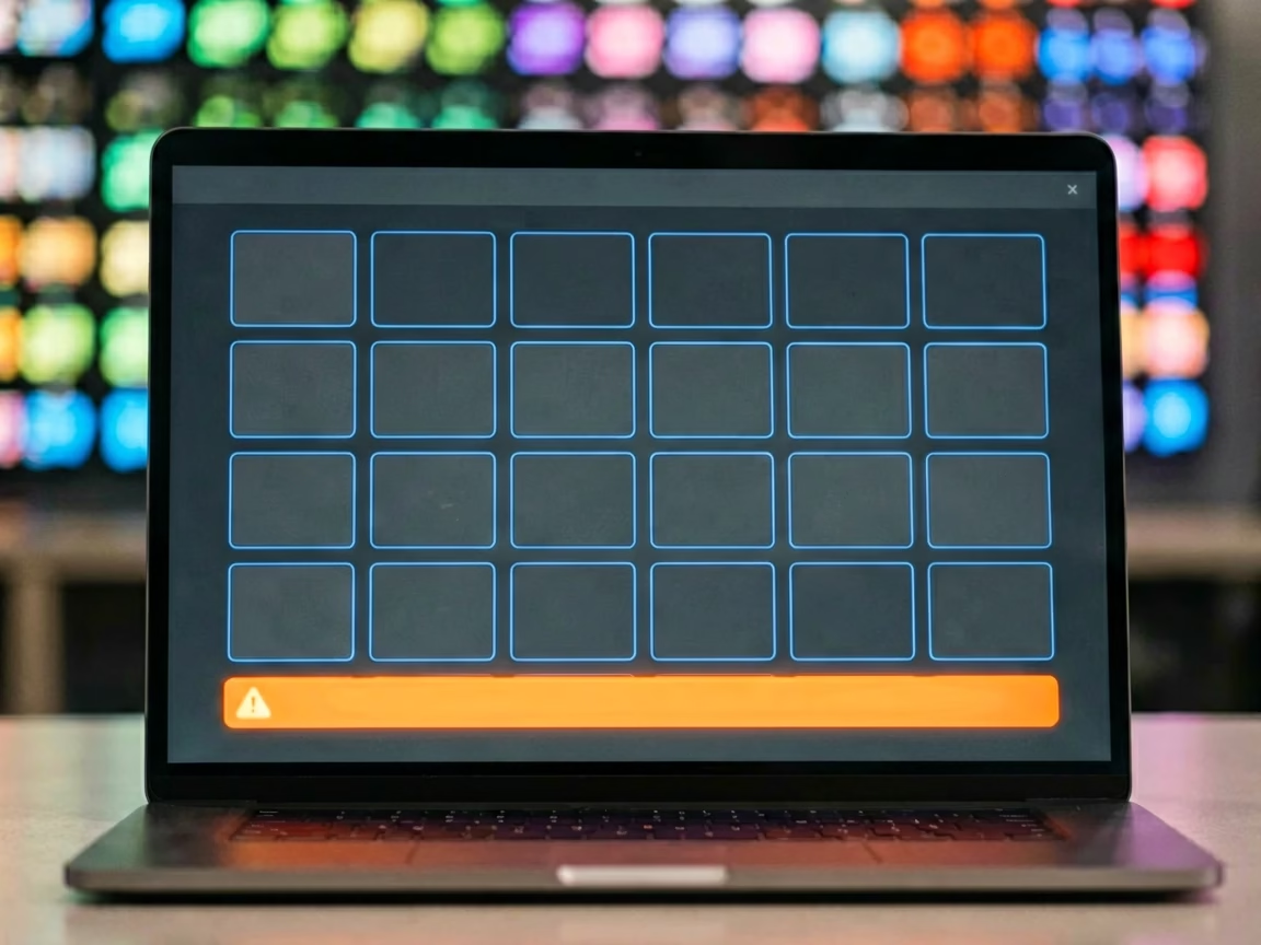
Colorlight’s official mapping tutorial — the shortest route from a jumbled wall to a correct image:
Colorlight Official — 05 Receiver Mapping Setting tutorial
What Does Save to Receiver Actually Write in a Colorlight LEDVISION Setup?
The save step is where setups are lost, because the software has three persistence levels and they are not interchangeable:
The field routine that closes the loop: Send to verify the image live, Save to Receiver to make it permanent, then export the configuration files to the PC and a USB drive. LEDVISION can also store a screen prestore on the card — a pre-loaded frame that displays while the wall boots — so a wall that has been configured once never shows an empty canvas after a power cycle. When a single card is replaced, the same save chain re-applies the configuration to that card alone, which beats re-detecting the whole wall. The full recovery workflow lives in the backup restore LED display hardware settings guide.
Colorlight’s official configuration-and-mapping walkthrough, from the screen settings screen to the saved receiver:
Colorlight Official — LEDVision EP07 Configuration and Mapping tutorial
Sending-card-side setup — input resolution, scaling and EDID — is a separate pass described in the how to configure LED sending card guide.
How Do You Maintain Calibration Coefficients in Colorlight LEDVISION?
Calibration coefficients are the per-pixel brightness and chroma correction data stored in each receiving card, applied at the factory and after on-site calibration to flatten brightness and color differences across modules. They live in the card, not in the software — so a card replacement wipes the on-site calibration unless the coefficients were backed up first. Since V8.8, LEDVISION includes a dedicated backup function for exactly this: calibration coefficient backup, plus receiver parameter backup and screen prestore.
The maintenance routine, done at handover and repeated before any card swap:
- Read back the coefficients stored in the receiving cards.
- Export them to a local file — keep it next to the mapping and configuration exports.
- After a card or module replacement, re-import the coefficients to the new card.
One detail that trips up restore jobs: seam correction coefficients carry position data — they must be re-imported to the same physical seam position they were exported from, or the seam correction applies to the wrong join. The current firmware generation adds the 9wPCoef coefficient format and the seamxCoef seam coefficient format, and newer builds can pull module calibration coefficients from the cloud when the original data is missing. If you plan to adjust brightness or color on an already-calibrated wall, read back and save the coefficients before touching anything.
Colorlight’s official calibration coefficient maintenance tutorial:
Colorlight Official — LEDVision EP09 How to Maintain Calibration Coefficients tutorial
For brightness problems that calibration cannot fix, the LED display uneven brightness troubleshooting guide separates coefficient issues from hardware faults.
How Does Redundant Firmware and Configuration Backup Protect a Colorlight LEDVISION System?
Firmware redundancy is a dual-bank boot design: the receiving card or sending card stores the firmware in two banks, and if the active bank is corrupted — a failed update, a power cut mid-write — the device boots from the backup bank instead of dying. Configuration redundancy is the same idea applied to the configuration parameters and calibration coefficients described above. Together with loop redundancy, receiving card redundancy and power supply redundancy, they form the six redundancy layers a Colorlight system can carry.
The maintenance rule that makes redundancy actually work: treat firmware, configuration and coefficients as one bundle.
- Firmware upgrades run through the LEDUpgrade tool; verify the redundant bank accepts the new build after the update.
- Configuration files come from the LEDVISION Save and export steps in Chapter 6.
- Coefficients come from the backup routine in Chapter 7.
When a card fails and a replacement goes in, the three restore in sequence — parameters and mapping first, coefficients second — and the wall returns to its calibrated state within minutes. The LED display system redundancy backup guide covers the loop and backup-port architectures that connect these layers. On the receiving card side, the Colorlight i6 LED receiving card specification lists redundant firmware as a built-in feature.
What Questions Do Technicians Ask About the Colorlight LEDVISION Setup?
What is the password for Colorlight LEDVISION screen settings?
The screen configuration password is 168 by default; some devices use 777. The same passwords gate LEDSetting’s screen configuration.
Why does LEDVISION not detect my sending card?
Check the physical chain first: direct Gigabit connection without a switch, the correct USB port (USB_IN, not USB_OUT) on USB cards, and the PC’s IP subnet versus the card’s default range. Detection problems are link-layer problems in most cases.
Which LEDVISION version should I install?
Match the hardware: older S2 and S4 sending cards run V5.0 to V7.0; current X-series and Z-series controllers need V8.0 or later for the calibration coefficient backup and receiver parameter backup functions.
Can I configure a module without a .rcfg file?
Yes — run the Intelligent Setting wizard, which reads the module’s data rows, scan mode and driver IC directly. Colorlight’s official wizard tutorial walks the full sequence, and the company’s one-minute video on sending parameters to a single receiving card covers the multi-card case where only one card needs the update.
What does the red capacity warning in receiver mapping mean?
The port’s mapped area exceeds the 655,360-pixel ceiling (1280×512) of a Gigabit port on X-series controllers. The fix is redistributing cabinets across ports or moving load to a controller with more ports — the X16, or the fiber-port Z6 PRO-G2 for large canvases.
What Should a Repeatable Colorlight LEDVISION Configuration Routine Look Like?
The colorlight ledvision setup guide reduces to a five-step routine you can run the same way on every wall: verify the direct Gigabit link and detect senders and receivers; load the correct .rcfg or run Intelligent Setting; match the data group layout; map the receiving cards from the front view and send; then save to the receivers and export the backup files. Two habits keep the wall healthy after that — backing up calibration coefficients before every card swap, and keeping firmware, configuration and coefficients together as one redundancy bundle. For the hardware decisions behind this workflow, the Colorlight X series selection guide and the Colorlight receiving card selection guide cover controller and card choice with the same official-document figures.
References & Sourced From: Colorlight LEDVISION Setup Guides
- Colorlight official download center — LEDVISION and LEDSetting software versions and release notes
- Colorlight LEDSetting User Manual V2.0 — receiver parameters, mapping and calibration coefficient export procedures
- Colorlight iSet User Manual V7.0 — calibration coefficient readback, export and save-to-receiver workflows
- Colorlight official YouTube series — LEDVision EP06, EP07, EP09; Data Group Swap and Split; Receiver Mapping Setting
- Community field procedures — WiredWatts Colorlight P10 configuration checklist; Colorlit LED receiver mapping walkthrough (used for procedure comparison, not linked)