
How Does an LED Display Work? The Complete Technology Guide
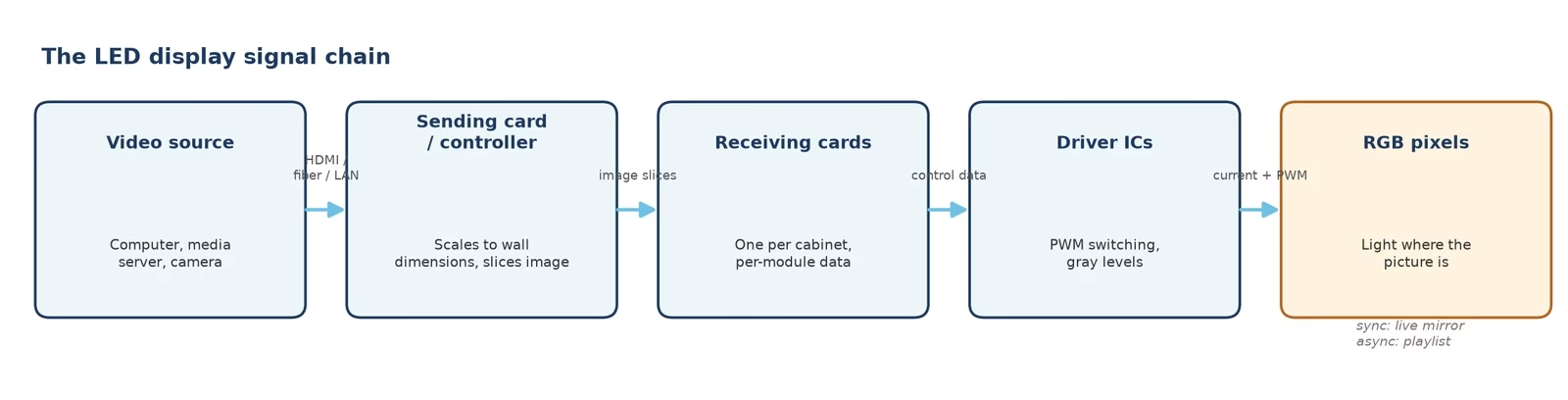
Quick answer: an LED display works by turning a video signal into millions of individually switched red, green, and blue diodes. A video source feeds a controller; the controller splits the image across receiving cards; each receiving card drives the driver ICs on the modules; and every driver IC switches its RGB pixels on and off thousands of times a second with precise current. Mix the three colors at the right brightness and the wall shows the image — no backlight, no liquid crystal, just light made where the picture is.
Every large screen you have seen in a stadium, a lobby, or on a building facade is built from the same recipe: light-emitting diodes arranged as pixels, a control chain that feeds them data, and driver electronics that switch each one with microsecond timing. This guide walks the full path — from the physics of a single diode to the finished wall, then through packaging, pitch, refresh, and the factory process that turns parts into a display. By the end, terms like receiving card, driver IC, scan rate, and COB will read like plain language.
1. What Is an LED Display?
An LED display is a flat-panel screen that uses light-emitting diodes arranged as its pixels: each diode is a semiconductor device that emits light when current flows through it. Because the diodes generate the picture themselves, a direct-view LED wall needs no backlight and no liquid-crystal layer — the two parts that make an LCD thick, dim at an angle, and limited in size.
Displays come in three generations of capability. Monochrome walls light one color (usually red or amber) for text and prices. Bicolor panels combine two colors for simple graphics. Full-color RGB walls — the standard today — place one red, one green, and one blue diode together as a single pixel, mixing millions of colors. Everything below describes the full-color kind, because that is what modern buyers spec.
2. How Does a Single LED Produce Light?
An LED is a light-emitting diode: a sandwich of semiconductor layers. When voltage pushes electrons across the junction between an n-type layer (electron-rich) and a p-type layer (hole-rich), electrons fall into holes and release their energy as photons — a process called electroluminescence. The first practical visible-light LED was demonstrated in 1962 by Nick Holonyak Jr. at General Electric, and the physics has not changed since; what changed is efficiency and packaging.
The color is fixed by the semiconductor’s chemistry, not by a filter: different band-gap materials emit different wavelengths. Gallium nitride-based chips produce blue and green; other compositions produce red. That is why an RGB pixel is three separate chips rather than one tunable lamp — each color needs its own material. It is also why LEDs are efficient: they make light directly from electron movement instead of heating a filament or exciting phosphors through a backlight chain, which is where LCD panels lose most of their energy.
3. From Three Diodes to One Pixel: The RGB Color Model
A full-color pixel is one red, one green, and one blue diode driven as a unit. The colors mix additively: red plus green reads as yellow, red plus blue as magenta, green plus blue as cyan, and all three at full drive as white. By varying the current — really the on-time, as Section 6 explains — each channel takes 256 levels at 8-bit depth, giving 256 × 256 × 256 = 16.7 million colors per pixel. Modern controllers process 14–16 bit per channel internally, which matters at low brightness: an 8-bit chain shows banding in dark lobby scenes, while a 16-bit chain keeps shadow detail smooth.
4. What Are the Parts of an LED Display?
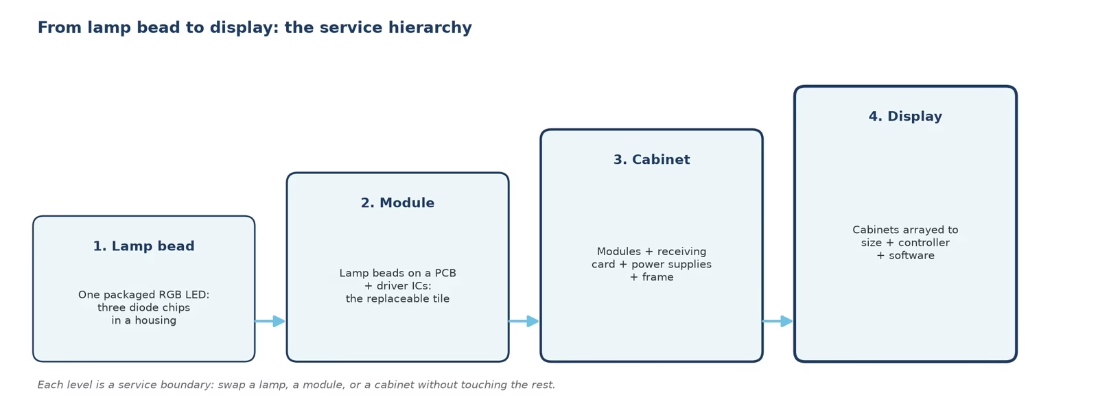
LED walls are built as a hierarchy, and every service conversation uses these names:
| Level | What it is | What it contains |
|---|---|---|
| Lamp bead | One packaged RGB LED | Three diode chips + plastic or epoxy housing |
| Module | The replaceable image tile | Lamp beads on a PCB + driver ICs + connectors |
| Cabinet | The structural building block | Modules + receiving card + power supplies + frame |
| Display | The finished wall | Cabinets arrayed to the target size + sending/controller + software |
Beyond the tiles themselves, a cabinet carries the parts that keep the picture stable: power supplies that hold voltage steady (flicker and color drift usually trace back here), data cables that carry pixel data cabinet to cabinet, cooling that keeps junction temperatures in their efficiency zone, and the frame that ties it all together — indoors as slim die-cast boxes, outdoors as sealed steel with weatherproofing.
5. How Does the Signal Chain Work?
The chain from content to light has four stations:
- Video source: a computer, media server, camera, or player outputs the content over HDMI, fiber, or a network.
- Sending card / LED controller: the controller decodes the signal, scales it to the wall’s exact pixel dimensions, slices the image across the wall, and streams the slices out. Synchronous systems mirror a live source in real time; asynchronous systems store a playlist on the controller and run on a schedule — the right choice depends on whether the wall mirrors a feed or plays scheduled content (our sending card configuration guide walks the setup).
- Receiving cards: one per cabinet (or per few), each takes its slice and translates it into per-module instructions — selecting a receiving card is a capacity question: pixel count, refresh target, and firmware features.
- Driver ICs and pixels: the driver ICs on each module switch every RGB diode with controlled current, thousands of times per second, producing the final image.
If any station loses data, the fault announces itself downstream as black sections, repeated blocks, or a frozen region — which is why our troubleshooting guide starts at the source and walks the chain.
6. How Do Driver ICs and Scanning Control Brightness?
Here is the part most guides skip, and it explains three specs on every quotation. An LED’s brightness is set by its current, but switching that current fully on and off is what produces gray levels: the driver IC applies PWM (pulse-width modulation), keeping each diode on for a precise slice of every cycle. Pack more, shorter pulses into each frame and you get more gray steps — 16-bit PWM divides each frame far finer than 8-bit, which is why premium ICs render dark scenes without banding.
Because one driver IC cannot wire every diode directly, modules are wired in scanned groups: a 1/32 scan means the driver lights one row group out of thirty-two at any instant, rotating fast enough that the eye sees them all lit. Scanning saves power and electronics, while the wall’s refresh rate — how many times per second the full image is repainted, from 1,920 Hz on office walls to 3,840–7,680 Hz on broadcast and rental screens — determines whether cameras see banding. The interplay of refresh, camera shutter, and content frame rate is its own topic; we break it down in Hz vs FPS.
7. Which Packaging Types Exist? DIP vs SMD vs COB vs GOB
The same diode chemistry ships in four packaging families, and the choice drives brightness, viewing distance, and durability:
| Packaging | Structure | Strengths | Typical use |
|---|---|---|---|
| DIP | Three discrete lamp legs through the PCB | Very bright, heat-tolerant | Legacy outdoor, long-throw billboards |
| SMD | One surface-mount package holds RGB chips | Fine pitch, mature cost curve | Most indoor and outdoor walls today |
| GOB | SMD + transparent resin seal over the face | Impact- and moisture-resistant | Rental, touch-prone, coastal sites |
| COB | Chips bonded directly to the PCB, then sealed | Finest pitch, best protection, low surface heating | Control rooms, premium fine pitch |
The trade-offs run deeper than this table — failure modes, repair economics, surface reflections — so we keep a dedicated SMD vs COB comparison for buyers choosing between them.
8. How Does Pixel Pitch Decide Resolution and Viewing Distance?
Pixel pitch is the center-to-center distance between adjacent pixels in millimeters, and it sets two things at once. First, pixel density: a P1.2 wall packs about 694,000 pixels per square meter, while a P10 wall carries 10,000 — a 69× difference in detail for the same area. Second, viewing distance: as a working rule, the minimum comfortable distance in meters is roughly the pitch number (P2.5 → about 2.5 m), with detail remaining satisfying out to several times that.
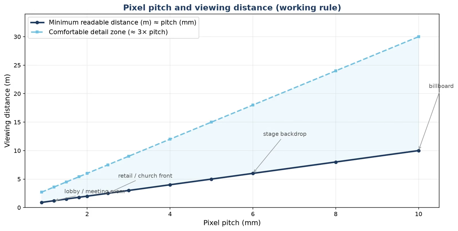
This is why pitch selection is an architecture decision, not a spec flex: a lobby viewed from 4 m wants P1.5–P2.5, a church wall viewed from 12 m is comfortable at P4–P6, and a highway billboard read from 80 m works at P10–P16. Buying finer pitch than the room needs spends budget on resolution nobody can resolve — our LED screen resolution guide and the 16:9 sizing guide translate pitch into exact cabinet counts and screen dimensions.
9. Direct-View LED vs OLED vs MicroLED
Three self-emissive technologies get compared in every purchasing meeting, and they differ in how the light is made and scaled:
- Direct-view LED: discrete inorganic diodes per pixel, assembled as modules and cabinets. Scales from a 1-meter board to a 200-meter facade with the same recipe — that scalability is unique to this family.
- OLED: organic films that emit per subpixel, delivering deep blacks in fixed panel sizes for TVs and phones. Panels cannot scale to wall dimensions, and static content ages them (we cover that mechanism in the burn-in guide).
- MicroLED: microscopic inorganic LEDs, self-emissive like direct-view but at consumer panel densities. Spectacular and expensive; manufacturing yield keeps it in premium niches while direct-view LED serves the large-format market today.
10. What Does the Factory Process Look Like?
Specifications describe the wall; the process behind them decides how it ages. A production line runs SMT placement of driver ICs and lamp beads, module assembly, and then two gates that separate serious factories from assemblers: a 72-hour full-brightness burn-in that eliminates early-life failures, and point-by-point calibration that matches brightness and color across every module before shipping. The clips below show both — first the line itself, then the finished-cabinet installation sequence from unboxing to calibration.
Ask any supplier two questions about this stage: what does your burn-in bench stress, and can your calibration report travel with the screen? The answers predict how the wall looks in year three.
11. FAQs About How LED Displays Work
Does an LED display need a backlight?
No. Direct-view LED pixels generate their own light; that is the core difference from LCD, which uses LEDs only as a backlight behind a liquid-crystal layer.
How does an LED display produce different colors?
Each pixel carries one red, one green, and one blue diode. Varying their drive levels mixes the three channels additively into millions of colors.
What does a receiving card do?
It takes its slice of the processed image from the controller and turns it into per-module data inside one cabinet, every frame, in sync with the rest of the wall.
What does a driver IC do?
It switches each LED with controlled current and PWM timing, setting the exact gray level of every diode thousands of times per second.
Why do LED screens flicker on camera?
The camera shutter samples the wall’s refresh cycle; when the refresh rate is low relative to the shutter, banding appears. Higher refresh (3,840 Hz and above) removes it.
What happens if one module fails?
Only that tile is affected. Because the wall is modular, the module is swapped and the region re-calibrated — no wall-level replacement.
What is pixel pitch and why does it matter?
It is the millimeter distance between pixel centers. It sets both pixel density and the minimum comfortable viewing distance, so it is the first spec to match to the room.
What is the difference between SMD and COB?
SMD places packaged RGB lamps on the PCB; COB bonds bare chips to the board and seals them. COB allows finer pitch and better protection; SMD is the mature, economical standard.
What is scan rate versus refresh rate?
Scan rate is how many row groups the driver serves per cycle (1/32, 1/16); refresh rate is how many times per second the whole image repaints. Both affect brightness stability and camera performance.
How far should you sit from an LED screen?
Rough rule: minimum comfortable distance in meters is about the pixel pitch number, with good detail out to several times that. A P2.5 wall reads well from about 2.5 m onward.
What is the difference between synchronous and asynchronous control?
Synchronous walls mirror a live source in real time for stages and broadcast; asynchronous walls store and schedule playlists on the controller for signage that runs unattended.
How long does an LED display last?
The diodes themselves decay gradually; industry lumen-maintenance testing (IES LM-80) measures that curve. With sane brightness and heat management, walls commonly serve 8–12 years before brightness planning matters more than failure rates.
12. Conclusion: One Chain, From Photon to Picture
An LED display works because a very old piece of physics — electrons releasing light in a semiconductor junction — is wired to a very modern control chain: a controller that slices the image, receiving cards that deliver it, driver ICs that pulse every diode with PWM precision, and a factory process that burns in and calibrates the result before it ships. Read a quotation with that chain in mind and the specs stop being alphabet soup: pitch answers where the audience stands, packaging answers how harsh the site is, refresh answers what the cameras will see, and modularity answers what happens in year five. If you are pricing a wall, our team — an LED screen manufacturer with the production line and calibration bench shown above — will map your room and content to the exact chain, from 3D outdoor billboards to fine-pitch lobbies.