
How Does a Video Wall Work? The Signal Chain From Source to Screen (2026)
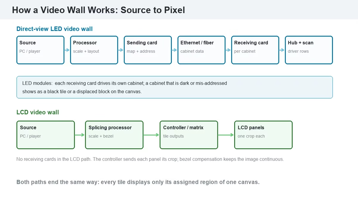
A video wall is a display system that tiles multiple panels or LED cabinets into one logical canvas. A processor maps a source across the tiles, a controller splits the canvas into tile-sized signals, and every tile is addressed to show only its section. On an LED wall the signal passes through a sending card, Ethernet or fiber, and a receiving card in each cabinet. On an LCD wall it passes through a splicing processor and a display controller. The wall looks like one screen because timing, geometry, and color are matched across tiles.
Short answer: How does a video wall work? It treats many displays as one canvas. A video source enters a video wall processor, which scales and positions it. The processor feeds a sending card or controller, which divides the canvas into tile-sized signals. On an LED wall, sending cards push data over Ethernet or fiber to receiving cards inside each cabinet, and those cards drive the LED modules. On an LCD wall, a splicing processor feeds each panel its section over HDMI, DisplayPort, or a daisy chain. Synchronization keeps every tile on the same frame, so the wall reads as one image instead of a grid of televisions.
1. How Does a Video Wall Work? The Short Answer
A video wall signal chain is the path from a source device to the pixels on each tile. It has five stages: source, processing, distribution, tile control, and display. Each stage has a different job, and a failure at any stage produces a different symptom. That is why a video wall is specified as a system, not as a set of screens.
Two architectures cover most projects. A direct-view LED video wall is an emissive wall built from LED cabinets, each with a receiving card that drives its modules. An LCD video wall is a matrix of commercial LCD panels driven by a splicing processor or video wall controller, with each panel showing a crop of the canvas. The signal path, failure points, and cost structure differ. Definitions and panel types are covered in what is a video wall; this guide follows the signal.
A video wall is not a large television split into parts. A television accepts one input and shows one image at its native resolution. A video wall accepts one or more sources, builds a canvas larger than any single panel, and assigns coordinates to each tile. The processor, not the panels, decides what appears where.
2. How Do Multiple Screens Form One Video Wall Canvas?
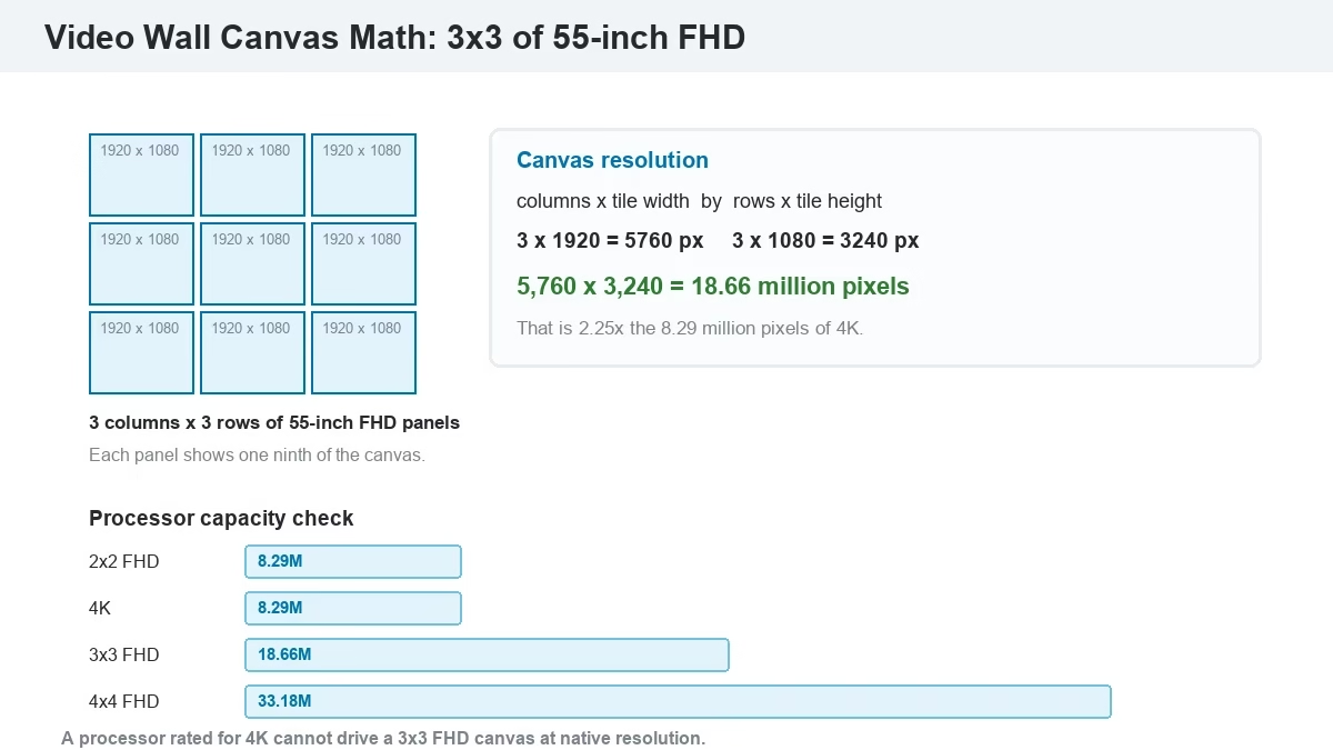
A video wall canvas is the logical image the processor draws before it is split. Its resolution is the tile width times the column count, by the tile height times the row count. A 3×3 wall of 55-inch 1920×1080 panels has a canvas of 5,760×3,240 pixels, or 18.66 million pixels. That is more than twice the 8.29 million pixels of 4K, which is why the processor matters as much as the panels.
| Wall configuration | Canvas resolution | Total pixels | Processor class |
| 2×2 of 55-inch FHD | 3,840×2,160 | 8.29M | 4K canvas |
| 3×3 of 55-inch FHD | 5,760×3,240 | 18.66M | Above 4K, multi-output |
| LED 6.4×3.84 m at P2.5 | 2,560×1,536 | 3.93M | Single 4K processor |
| LED 6.4×3.84 m at P1.86 | 3,441×2,064 | 7.10M | Single 4K processor |
How Do You Calculate Video Wall Canvas Resolution?
Canvas resolution is columns × tile width by rows × tile height. For LED, tile width is the cabinet width in millimeters divided by the pixel pitch. A 640 mm cabinet at P2.5 is 256 pixels wide; ten columns give 2,560 pixels. Cabinet counts must be whole, so the canvas is set by the cabinet grid, not by the nominal room width. The LED screen size guide covers the cabinet arithmetic, and the P2.5 viewing distance guide covers the pitch-to-distance rule.
3. What Does a Video Wall Processor Do Between Source and Screen?
A video wall processor is the device that accepts sources, scales them, arranges them in windows, and outputs the canvas to the display system. It performs five functions: input switching, scaling, window layout, switching without a black frame, and EDID management. It also sets the output timing that the sending card or display controller follows.
The processor is not a matrix switcher. A matrix switcher routes one input to one output; it does not scale or compose. A processor takes several inputs, composites them into a canvas, and sends that canvas onward. Buying a matrix switch and expecting it to place four sources on a 3×3 wall is a common mistake.
The processor’s rated pixel capacity must exceed the canvas. A 3×3 FHD wall needs more than 18.66 million pixels of output capacity, which usually means multiple 4K outputs or a multi-controller design. For LED walls, the processor’s output feeds a sending card, and the sending card has its own pixel and port limits. Size both, not just one. The LED video processor collection and the MCTRL4K vs VX4S comparison show how the two classes differ.
4. How Do Sending Cards and Receiving Cards Drive an LED Video Wall?
A sending card is the interface that converts the processor’s video output into LED data and distributes it over Ethernet or fiber. A receiving card is the controller inside each cabinet that accepts that data, stores the cabinet’s parameters, and drives the LED modules through hub and scan boards. The pair is the core of an LED video wall’s distribution stage.
The sequence is: the processor outputs HDMI or DVI to the sending card; the sending card maps the canvas into cabinet-sized regions; each region travels over Gigabit Ethernet or fiber; the receiving card in the matching cabinet decodes its region; the hub board fans the data to the module rows; the scan board switches the driver ICs; the LEDs emit. The receiving card stores the cabinet’s calibration data, so a replacement card is reloaded from a file rather than recalibrated from zero.
Addressing decides whether the wall shows one image or a scrambled grid. Each receiving card is assigned an address that maps to a canvas coordinate. In NovaStar systems this mapping is done in NovaLCT; in Colorlight systems it is done in LEDVISION. The guide to configuring an LED sending card and the Colorlight LEDVISION setup guide walk through the mapping. For control hardware, see the LED screen display control system collection and the NovaStar LED display controller range.
What Is the Difference Between a Sending Card and a Video Processor?
A video processor decides what the canvas contains: it scales sources, places windows, and sets output timing. A sending card decides how that canvas reaches the cabinets: it splits the canvas into regions, assigns addresses, and transmits the data. A processor without a sending card has no way to reach LED cabinets; a sending card without a processor can pass a source to the cabinets but cannot place multiple sources in windows.
5. How Does an LCD Video Wall Work Without Receiving Cards?
An LCD video wall is a matrix of commercial LCD panels fed by a splicing processor or video wall controller. Each panel has its own scaler and input, so there is no cabinet-level receiving card. The controller outputs a separate signal to each panel, or daisy-chains panels over DisplayPort MST. Each panel displays the crop of the canvas assigned to its position.
Because the panel does the scaling, edge behavior matters. Bezel compensation shifts each crop so content lines up across the joints; without it, a face crossing a seam is cut in half by the bezel width. A 3×3 wall needs a controller rated for 18.66 million pixels, not a 4K switcher with nine outputs.
Three key differences separate the two signal paths:
- LED walls address each cabinet; LCD walls address each panel.
- LED walls use sending and receiving cards; LCD walls use a splicing processor and per-panel inputs.
- LED walls have no bezel; LCD walls need bezel compensation at every joint.
A consumer television is not an LCD video wall panel. Consumer sets lack the commercial duty rating, narrow bezel, RS-232 or LAN control, and color-matching controls.
6. How Do Video Wall Tiles Stay in Sync Without Tearing?
Synchronization is the process that holds every tile on the same frame. It depends on a shared clock, a common output timing, and a distribution design that does not let one branch run ahead. When sync fails, a moving object tears at a tile boundary or one section lags.
In an LED wall, the processor locks to the source, the sending card locks to the processor, and the receiving cards lock to the sending card’s data stream. Sending cards in a cascade share a reference, and genlock can lock the wall to an external house clock. In an LCD wall, the splicing processor outputs all tiles from one frame buffer, so panels stay aligned when they share output timing and refresh rate.
Two distribution architectures have different latency profiles. AVSM (audio-video signal management) sends uncompressed signals over a dedicated matrix and adds roughly 1–3 frames. AVoIP encodes the signal into IP packets and decodes it at the display; latency is typically 2–10 frames depending on codec and network design (Kramer, 2026). Low-latency control rooms stay on AVSM; distributed campuses accept AVoIP for distance and flexibility.
What Is Genlock and Why Does a Video Wall Need It?
Genlock is a synchronization signal that forces a display processor to follow an external reference clock. A video wall needs it when the wall appears on camera, when it shares content with a broadcast switcher, or when several processors feed different sections. Without genlock, the wall and the camera run on independent clocks, and the screen flickers or rolls in the recording even though it looks stable to the eye.
7. How Does Video Wall Software Map and Control the Canvas?
Video wall software is the configuration layer that maps cabinets, sets brightness and color, and saves layouts. On LED walls, NovaStar’s NovaLCT and SmartLCT and Colorlight’s LEDVISION are the common tools. They assign receiving-card addresses, define the cabinet grid, set the sending card’s output, run test patterns, and store calibration files.
On LCD walls, the controller software defines the panel grid, bezel compensation, input routing, and window presets. Content management software sits above both and decides what plays: a single video stretched across the wall, several windows, or a scheduled playlist. The wall works as one screen only when the mapping and content layers agree on canvas size and aspect ratio.
8. How Does a Video Wall Send Signal Across Long Distances?
Signal distribution is the link between the processor and the tiles, chosen by distance, resolution, and latency. Copper HDMI is reliable to about 5–10 m passive and 15–30 m active. SDI carries 3G/12G video over 100 m or more of coaxial cable. HDBaseT extends HDMI over twisted pair to about 100 m. Fiber reaches kilometers and isolates ground loops. Ethernet is limited to 100 m per copper hop, which is why large LED walls use fiber between distant cabinets.
For an LED wall, the sending card usually outputs Gigabit Ethernet to the first cabinet and daisy-chains to the rest. Each receiving card has two ports, in and out, so the data passes through in sequence. The number of cabinets per port is limited by the card’s pixel capacity and the cable length. For a long wall, the design uses multiple ports or fiber transceivers rather than one long chain.
What Is AV-over-IP in a Video Wall?
AV-over-IP is a distribution method that encodes video and audio into IP packets, sends them over a standard network switch, and decodes them at the display. It lets one source reach many screens, and many sources reach one wall, over existing network cabling. The trade-offs are compression artifacts, network configuration, and higher latency than a dedicated matrix.
9. How Do Pixel Pitch and Viewing Distance Change How a Video Wall Works?
Pixel pitch is the distance between adjacent LED clusters. It sets how much detail the wall can show at a given distance, and it sets the canvas resolution for a given cabinet size. A 6.4×3.84 m wall at P2.5 is 2,560×1,536 pixels; the same wall at P1.86 is 3,441×2,064. The finer wall carries more pixels but costs more per square meter.
| Pitch | Minimum viewing distance | Pixels per ㎡ | Typical role |
| P1.5 | ~3 m | 444,444 | Boardrooms, close-view lobbies |
| P1.86 | ~4 m | 289,000 | Lobbies, flagship retail |
| P2.5 | ~5 m | 160,000 | Churches, halls, mid-size venues |
| P3.91 | ~8 m | 65,536 | Stages, rental, event floors |
| P10 | ~20 m | 10,000 | Billboards, long-distance signage |
The wall shows a usable image only when the source resolution matches the canvas. A 1080p source on a 2,560×1,536 canvas is upscaled, and the extra pixels are interpolated, not real. A 4K source on the same canvas is downscaled, which is cleaner than upscaling. Feed the wall at its native canvas size when the processor allows it.
10. How Is a Video Wall Commissioned to Work as One Screen?
Commissioning proves the wall works as one display: every cabinet mapped, every source tested, every seam checked, and color matched. It starts with test patterns and ends with a handover that lists the canvas resolution, input map, and saved calibration files.
The sequence is: run red, green, blue, and white fields to find dead pixels and color patches; run a grayscale ramp to check low-gray uniformity; verify the cabinet map against the physical grid; set brightness and gamma; calibrate color across cabinets; test every input and window preset; check sync under motion; and save the configuration. The video below shows wiring, receiving-card addressing, and test-pattern steps in a real indoor build.
Keep the saved configuration. A receiving card replacement is a file reload, not a recalibration, when the cabinet’s data was stored and labeled. The P1.86 indoor fine pitch LED display, P2.5 indoor LED display, and P3.91 indoor rental LED display pages list the cabinet formats and service access for each family.
11. Why Does a Video Wall Stop Working, and How Do You Diagnose It?
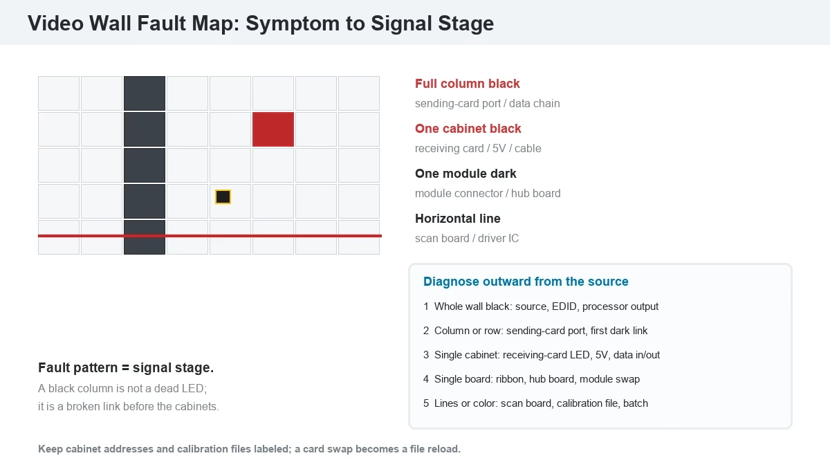
A video wall fault is a symptom that maps to a stage in the signal chain. The pattern of the failure is the diagnostic clue: a whole column, one cabinet, one module, or the entire wall. Work from the source outward, and test one stage at a time.
| Symptom | Likely stage | First check |
| Entire wall black | Source or processor output | Input signal, EDID, processor output LED |
| One full column or row black | Sending card port or data chain | Ethernet link at the first dark cabinet, port map |
| One cabinet black | Receiving card, power supply, or data cable | Status LED on the receiving card, 5V output |
| One module or board dark | Module connector or hub board | Reseat the ribbon, swap the module |
| Horizontal line or band | Scan board or driver IC | Scan board seating, driver output |
| Tearing or lag at a seam | Sync or output timing | Genlock, refresh match, sending-card cascade |
| Color patch on one tile | Calibration or bin mismatch | Reload cabinet calibration file, check batch |
The full diagnostic flow is in the LED display troubleshooting guide. Camera-only flicker is a separate problem: it comes from a refresh rate below the shutter speed, not from a failed card, and it is covered in fix LED screen flickering.
12. How Does a Video Wall Handle 4K, HDR, and High Refresh Content?
4K video wall content is a 3,840×2,160 source, or 8.29 million pixels. On a larger canvas, the processor upscales it or splits it across multiple 4K outputs; on a smaller canvas, it downscales. The processor, sending card, and receiving cards must support the resolution and frame rate end to end; one 1080p link caps the wall.
HDR adds a wider brightness range and 10-bit color. It works only when the source, processor, sending card, receiving card, and LED driver all carry the metadata and bit depth; an 8-bit pipeline shows banding. High refresh means 3,840 Hz or more, which matters when cameras point at the wall. A 1,920 Hz wall looks fine to the eye and bands on camera; 3,840 Hz with a high scan mode is the baseline for broadcast and events.
13. What Are the Most Common “How Does a Video Wall Work” Questions?
How does a video wall work without a computer?
A video wall can run without a computer when the processor has a built-in player or the sending system supports USB and network playback. The processor still builds the canvas; the source is a media file rather than a live computer output.
What equipment is needed for a video wall?
An LED wall needs cabinets, a sending card, receiving cards, a processor, a structure, power, and control software. An LCD wall needs panels, mounts, a splicing processor or controller, and cabling.
Can I use regular TVs for a video wall?
Regular TVs can be tiled, but they lack commercial duty ratings, narrow bezels, control ports, and color-matching controls. Seams and brightness drift become visible, and the warranty usually excludes continuous operation.
Why does my video wall show a black cabinet?
A black cabinet usually means a receiving card, power supply, or data cable fault. Check the receiving card status LED first, then the 5V supply, then the incoming and outgoing Ethernet links.
How does a video wall stay in sync?
Every tile follows a shared clock and common output timing. Sending cards cascade from one reference, LCD controllers output all tiles from one frame buffer, and genlock locks the wall to an external source when cameras are involved.
14. References & Sourced From: Video Wall Signal Chain and Display Technology
- Haivision, “Video Wall System Basics,” 2026.
- Kramer AV, “What is a Video Wall? Its tech (AVSM vs AVoIP) and use cases,” 2026.
- Mvix, “What Is A Video Wall & How Does It Work?” 2020, updated 2026.
- Unilumin, “Everything You Ever Wanted to Know About LED Video Walls,” 2024.
- Samsung Insights, video wall display data, 2023.
- NovaStar and Colorlight control-system documentation, 2026.
- UnifyLED product and control-system data, 2026.
15. Conclusion: How Does a Video Wall Work From Source to Pixel?
How a video wall works comes down to one path: source into a processor, processor into a controller or sending card, sending card into receiving cards, and receiving cards into pixels. Canvas, mapping, sync, and calibration make many tiles read as one screen. Specify the canvas resolution first, size the processor and sending card to it, map every cabinet, and save the configuration. For the budget side, read how much does a video wall cost. For a signal-chain review, send the canvas size, cabinet count, and source list to an LED screen manufacturer.