
P4.81 LED Module Hot Swap Guide: Replace Modules Without Powering Down
Published: July 2026 | Reading time: 13 min | UnifyLED Engineering Team
A P4.81 LED module hot swap is the procedure of replacing a faulty LED module on a P4.81 display while the rest of the screen remains powered on and operational. For rental staging companies running live events, outdoor billboard operators managing 24/7 advertising inventory, and control room technicians maintaining mission-critical video walls, the ability to swap a damaged module without shutting down the entire display is not a convenience — it is an operational requirement. A 10-second hot swap versus a 20-minute full power cycle means the difference between an invisible repair during a live show and a visible service interruption that disrupts the audience experience or advertising revenue. This guide covers the complete P4.81 hot swap procedure, including tool requirements, connector handling, safety protocols, and post-swap calibration.
The P4.81 pixel pitch (4.81mm between LED centers, approximately 43,264 pixels per square meter) is the most widely deployed outdoor rental and fixed-installation pitch globally. Its modules — typically 250×250mm with SMD 2727 or SMD 3535 LED packages — are designed with magnetic front-attachment and tool-less connector systems specifically to enable field-level hot swap capability. Understanding the connector architecture, magnetic latch mechanism, and calibration requirements is essential for any technician responsible for P4.81 display maintenance. See LED screen maintenance for comprehensive preventative maintenance schedules.
What Is the P4.81 LED Module Hot Swap Anatomy? Connectors, Latches & Compatibility
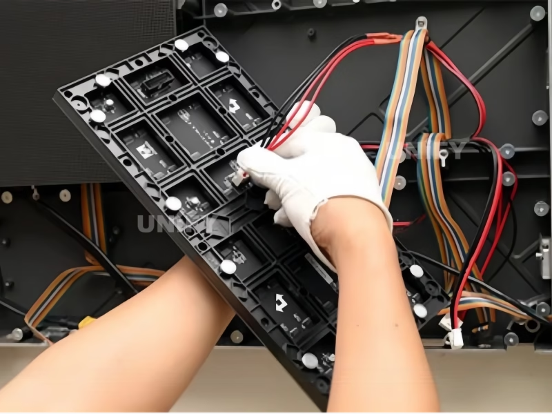
Before attempting a hot swap, you must understand the physical architecture of a P4.81 LED module. The standard P4.81 outdoor module measures 250×250mm and connects to the cabinet frame through two systems: a magnetic latch array for mechanical attachment and a pin-header connector pair for electrical connection. These two systems must be engaged and disengaged in the correct sequence to avoid damaging the module, the cabinet, or the connectors.
1.1 Magnetic Latch System
P4.81 modules are secured to the cabinet frame by 4–6 neodymium magnets embedded in the module’s rear plate, which mate with corresponding steel pads on the cabinet cross-members. These magnets provide approximately 15–20 kg of holding force per module — sufficient to keep the module firmly seated against wind load and vibration, but releasable with a standard magnetic removal tool (suction cup or magnetic puller). The magnets have no mechanical wear parts and are rated for 10,000+ attachment cycles. When hot-swapping, the magnetic attachment is released first, then the connectors are separated — never pull a module by its cables.
1.2 JST VH Connector System
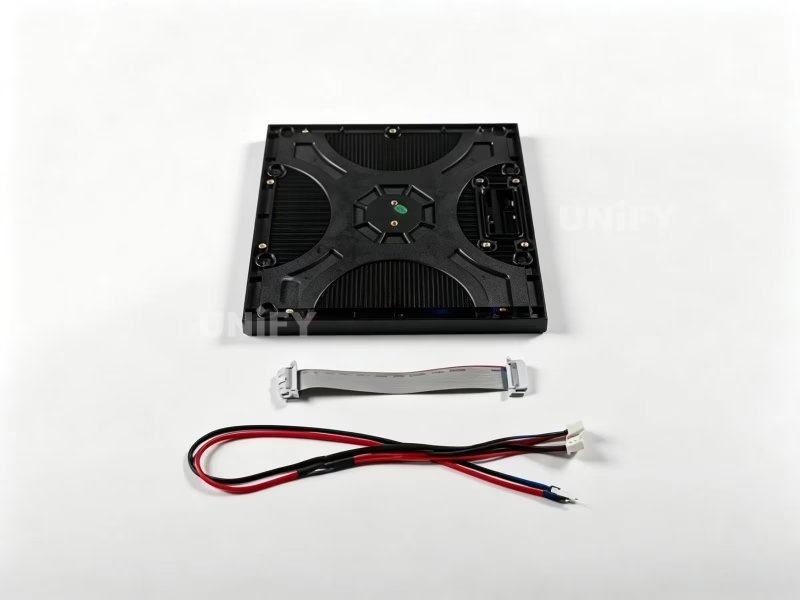
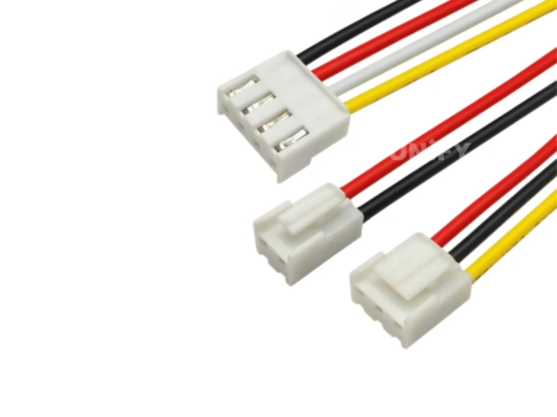
The electrical interface uses JST VH-series connectors — a polarized, locking pin-header system rated for 7.5A per circuit at 250V. A standard P4.81 module has two connectors: a 4-pin power connector (VCC, GND, GND, VCC — redundant ground for outdoor reliability) and a 16-pin or 20-pin signal connector carrying RGB data, clock, latch, and OE signals from the receiving card. The JST VH locking tab must be depressed before the connector can be separated — pulling without releasing the lock damages the connector housing and can crack the PCB solder joints. This is the most common technician error during hot swap procedures.
1.3 Module Compatibility Verification
Before hot-swapping, verify that the replacement module matches the existing modules in four parameters: pixel pitch (must be 4.81mm), LED package (SMD 2727 for outdoor, SMD 2121 for indoor), scan mode (typically 1/13 or 1/16 for P4.81), and driver IC model. A module with a different scan mode or driver IC will display incorrectly — showing brightness mismatch, color cast, or partial display failure — even though it physically fits the same cabinet. Module specifications are printed on a label affixed to the rear plate. Cross-reference the label with the original module before installing. For detailed guidance on LED pixel pitch identification, see our specification reference.
What Tools Do You Need for P4.81 LED Module Hot Swap? Safety Checklist
Hot swap means the display is energized. This introduces electrical safety considerations that do not apply during a powered-off module replacement. The following equipment and precautions are mandatory.
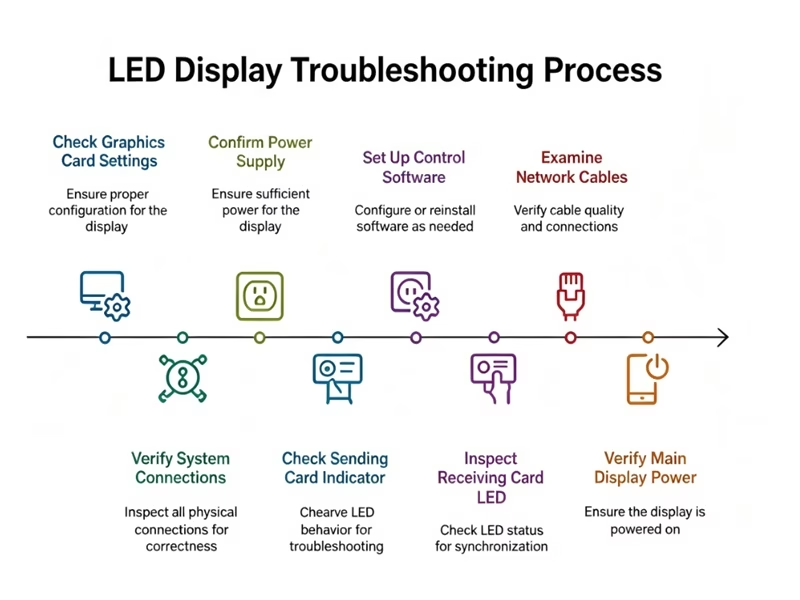
Essential tools: Magnetic module removal tool (suction cup type, rated for 20 kg pull force) — $15–$25; anti-static wrist strap with grounding clip — the display frame provides a convenient ground point; replacement P4.81 module of matching specification; insulated needle-nose pliers (for connector handling near live circuits); LED module test fixture or spare receiving card for bench-testing the removed module later; NovaLCT-loaded laptop (for post-swap calibration if needed). See LED screen flickering for diagnostic procedures if the new module shows flicker after installation.
Safety rules: (1) Wear anti-static protection — the human body can carry 5,000–25,000V of static charge, sufficient to destroy LED driver ICs on contact. (2) Do not touch exposed PCB traces or connector pins while the display is powered — the 5V DC rail is low voltage but the constant-current driver circuit can deliver up to 60mA per channel, and a short across data lines can propagate back to the receiving card and damage it. (3) If the module to be replaced shows signs of water ingress, corrosion, or burn marks, power down the entire cabinet before removal — a shorted module can draw excessive current that damages the receiving card’s output port if disconnected under load. (4) Work from a stable platform — ladder or mobile scaffold rated for the working height. Never perform a hot swap while balanced on an unstable surface.
How to Perform P4.81 LED Module Hot Swap: Step-by-Step Guide
The following procedure assumes a standard front-access P4.81 outdoor rental cabinet with magnetic module attachment. The UnifyLED demonstration below shows the complete module replacement workflow on an Ehonor series display.
UnifyLED — UnifyLED — How to Replace an Ehonor LED Module
Identify & Inspect the Faulty Module
Verify the module truly requires replacement — not a loose connector, signal cable fault, or receiving card issue. Run a test pattern (solid red, green, blue, white) from the control software. If the module shows partial failure (dead rows/columns, color cast on specific LED groups) rather than complete blackout, the driver IC is likely at fault and the module must be replaced. If the module is completely dark but adjacent modules are operational, check the power connector before assuming module failure.
Release Magnetic Latches
Position the magnetic removal tool (suction cup) on the center of the module face. Apply steady, perpendicular pull force — approximately 15 kg — until the magnets release. Do not twist, lever, or pry from the edges — this cracks the module PCB and damages the LED lenses. The module should detach cleanly from all four corners simultaneously. If one corner resists, the cabinet frame may be deformed — stop pulling, inspect the frame, and if necessary loosen the adjacent module first to relieve frame stress.
Disconnect JST Connectors — Lock Tab First
With the module partially separated from the frame (magnets released, connectors still engaged), locate the JST VH connector locking tabs. Depress each tab with your thumb while gently pulling the connector housing — never the wires — until the connector separates. Disconnect the signal connector first, then the power connector. Reconnecting during reassembly follows reverse order: power first, then signal. This sequence prevents the receiving card from attempting to drive an unpowered module if the signal connects before power.
Install Replacement Module
Verify the replacement module’s specification label matches the original. Connect power cable first — listen for the JST lock tab click. Connect signal cable second. Before seating the module against the frame, visually verify that no cables are pinched between the module PCB and the cabinet cross-members. Align the module edges with the surrounding modules, then press firmly at all four corners until the magnets engage. The module should sit flush with adjacent modules — if it protrudes or sits recessed, the magnets may have captured debris or the frame may require adjustment. See LED display configuration for alignment procedures.
Verify Operation & Run Test Pattern
The replacement module should display content immediately upon connection — no reboot, configuration change, or calibration required for basic operation. Run red, green, blue, and white test patterns sequentially and inspect for dead pixels, color uniformity, or brightness mismatch with surrounding modules. If the module shows a visible brightness or color difference, proceed to Section 6 for calibration. If the module shows no light at all, power-cycle the cabinet — a receiving card may require a reset to recognize a newly connected module on some controller configurations.
How Does Front vs Rear Access Affect P4.81 LED Module Hot Swap?

P4.81 displays support two module access methods. Front access (magnetic): The module is removed from the display face using a suction cup or magnetic puller. This is the standard method for rental cabinets and flush-mounted fixed installations where rear access is impossible. The 5-step procedure in Section 4 applies. Hot swap is supported — the module disconnects and reconnects without affecting adjacent modules. For cabinet architecture details, see LED screen cabinet.
Rear access (screw-fastened): Some fixed-installation P4.81 designs use screws rather than magnets to secure modules. These modules can only be accessed from behind the display. Rear-access hot swap is possible but requires physical access to the back of the cabinet — typically through a maintenance corridor or by removing rear cabinet panels. Rear-access modules use the same JST VH connectors and follow the same connection/disconnection sequence. The primary operational difference: rear-access hot swap requires two technicians (one rear for connectors, one front for module alignment) or a single technician moving between front and rear.
How to Calibrate and Test After P4.81 LED Module Hot Swap Replacement
A brand-new P4.81 module will rarely match the brightness and color characteristics of modules that have been in service for months or years. LED aging — specifically the non-linear luminance decay curve that drops 2–5% in the first 1,000 hours then stabilizes — means a replacement module typically appears brighter and slightly cooler in color temperature than its aged neighbors. This mismatch is visible to audiences at close range and must be corrected.
Immediate correction: In NovaLCT, navigate to Screen Configuration → Brightness → Manual Adjustment. Select the newly installed module’s position and reduce its brightness by 3–8% to visually match surrounding modules. This is a temporary fix suitable for live events where calibration hardware is unavailable.
Permanent correction: Schedule a full calibration session using NovaCLB with a supported colorimeter (X-Rite i1 Pro or equivalent). The calibration system measures every pixel’s actual luminance and chromaticity, computes per-pixel correction coefficients, and uploads them to the receiving card. This process takes approximately 30–60 minutes for a standard P4.81 display and should be performed during the next scheduled maintenance window. Calibration data persists through power cycles. See LED screen brightness for calibration methodology and LED display power consumption for the impact of calibration on energy use.
When Should You Hot Swap vs Power Down for P4.81 LED Module Replacement?
Hot swap is not always the correct choice. The following decision framework prioritizes technician safety and equipment protection over uptime convenience.
The critical rule: if the faulty module shows any evidence of electrical fault (burn marks, scorching, melted connector housings, or visible water inside the module), do not attempt hot swap. A shorted module can draw enough current through the receiving card’s output port to damage the card. Power down the entire cabinet, replace both the module and the affected cables, and bench-test the receiving card before reapplying power. For diagnostic procedures, see basic debugging of LED displays.
FAQ: P4.81 LED Module Hot Swap – Common Questions Answered
Why P4.81 LED Module Hot Swap Saves Time and Reduces Downtime
The P4.81 LED module hot swap is a 60-second procedure that saves 20 minutes of downtime per module failure. For a rental staging company running 50 events per year with an average of 2 module failures per event, hot swap capability saves approximately 33 hours of cumulative downtime annually — time that directly translates to revenue-generating event availability. For an outdoor billboard operator running 24/7 advertising, hot swap means a failed module is invisible to the advertiser — replaced during a scheduled maintenance walk rather than requiring an emergency service call.
The procedure itself is mechanically simple: identify the faulty module, release magnets, disconnect JST connectors (signal first, power second), connect replacement (power first, signal second), seat magnets, verify. The skill lies in the judgment — knowing when a hot swap is safe versus when a module showing electrical fault requires a full power-down — and in the post-swap calibration that restores visual uniformity. Master both, and you eliminate module failure as a source of audience-visible downtime.
Need P4.81 Spare Modules or Technical Support?
UnifyLED stocks P4.81 replacement modules, magnetic removal tools, and JST connectors — factory-direct pricing with global express delivery.
Get a Free Quote for Spare Modules
legidatechled@gmail.com | +86-191-18802497