
Colorlight i9 LED Receiving Card
The Colorlight i9 LED Receiving Card is Colorlight’s high-end SODIMM-format receiving card for fine-pitch and rental displays: a 384×256-pixel load with 32 parallel or 64 serial data groups, HDR10 and HLG support, 120–240Hz refresh, 65,536 grayscale levels and 14-bit calibration — on a 67.6×35.5mm, 9.5g card that plugs straight into the HUB board.
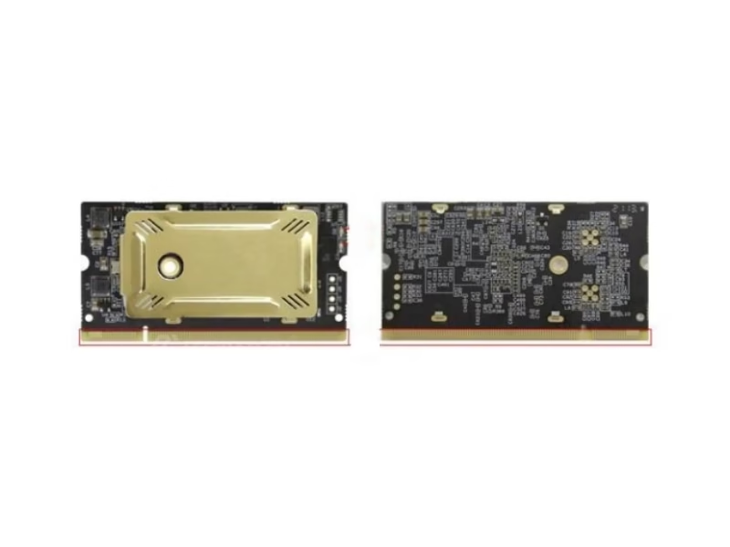
What Is the Colorlight i9 LED Receiving Card?
The Colorlight i9 LED Receiving Card is a high-end receiving card built for fine-pitch LED screens and premium rental cabinets. Its defining traits: a DDR2-200 SODIMM connector that plugs directly into the HUB board, a 384×256-pixel load with 32 parallel or 64 serial RGB data groups, HDR10 and HLG display with 30-bit input, 120–240Hz refresh, and 65,536 grayscale levels with 14-bit calibration. The i9’s newer generation, the i9+, extends the platform to 256×1024 pixels and 128-scan support — the comparison section below separates the two generations, because marketplace listings frequently mix their figures.
Short answer: The Colorlight i9 is a 67.6×35.5mm, 9.5g SODIMM receiving card with a 384×256-pixel full-color load, 32 parallel / 64 serial data groups, HDR10 + HLG with up to 30-bit input, 120–240Hz refresh, 65,536 grayscale levels, 14-bit point-by-point calibration, static-to-64-scan support, and five monitored power channels with dual-card hot backup — all confirmed against the official Specification V1.4.1 pin definitions.
A note on data sources: the official i9 Specification V1.4.1 renders its overview pages as images, while the connector pin definitions are fully extractable — and those pin tables are the most valuable part of the document, because they confirm hardware facts no listing states: 64 data channels (DATA1–DATA64), five power-monitoring inputs (Power_M1–M5), dual-card backup lines (RCV_BK1/RCV_BK2) and temperature, humidity and fan monitoring signals (LED_TEMP/LED_HUM/LED_FAN). Specifications on this page combine those official pin facts with cross-verified distributor data; conflicting figures are documented in the correction table.
Colorlight’s official receiving card family introduction:
Colorlight Official — InfoComm 2018 Colorlight Introduces Receiver Cards video
What Are the Colorlight i9 LED Receiving Card Specifications?
Official Specification V1.4.1 pin facts plus cross-verified distributor data (colorlight.net / eager-led / jekazled — consistent across sources).
Control & Display Quality
Monitoring & Backup (Official V1.4.1 Pin Facts)
Physical & Electrical
Why Do Colorlight i9 LED Receiver Card Spec Sheets Disagree?
In August 2026 listings we reviewed, the i9’s loading capacity appears in three versions — and one of them belongs to a different card. Verified against the official Specification V1.4.1 and cross-verified distributor data:
Why these errors cost money: a wall planned against a misattributed 256×1024 needs far fewer cards than reality delivers at 384×256 — the card count comes up short at installation. The production-status confusion is the same story: the i9+ is the current generation, and the i9 remains available through genuine channels. Verify the generation a quote describes, the way you would for any two-generation product line.
How Does the Colorlight i9 LED Receiving Card Compare to the i9+?
Two generations share the i9 name. The i9+ is the current platform — and most “i9” listing errors trace back to its figures:
The decision in three numbered differences:
- Capacity and scan. 384×256 and 64-scan on the i9 versus 256×1024 and 128-scan on the i9+ — the i9+ doubles the scan range and reshapes the load for ultra-fine-pitch modules.
- Data groups. 64 serial groups on the i9 versus up to 128 on the i9+ — the newer platform drives the highest-density module designs.
- Monitoring depth. Both carry the five-channel power monitoring; the i9+ extends cabinet monitoring with door, fan and smoke channels.
For the sibling cards in the Colorlight receiving line, the i5A-905 and i5A-F pages complete the selection ladder.
What Do the Official Pin Definitions Reveal About the Colorlight i9 LED Screen Receiving Card?
The official Specification V1.4.1’s connector pin table — the fully extractable part of the document — confirms hardware capabilities that no marketplace listing states:
DATA1–DATA64 — the 64 serial data channels, confirmed
Sixty-four named data lines on the SODIMM pinout are the hardware proof of the 64-serial-group capability — the foundation of the i9’s creative-display and high-density module support.
Power_M1–M5 — five voltage-monitoring channels
Five dedicated power-monitoring inputs mean the card watches five supply rails in the cabinet — a monitoring depth most receiving cards reach only with a multifunction card bolted on.
RCV_BK1 + RCV_BK2 — dual-card hot backup, on the pins
Two named backup lines are the physical implementation of the dual receiving card hot backup — two cards per cabinet, take-over on failure, wired at the connector level.
LED_TEMP · LED_HUM · LED_FAN — environment sensing on the card
Temperature, humidity and fan signals appear by name in the pin table — cabinet environment monitoring is native hardware, not an add-on. UART/I2C lines and the status LEDs complete the field-diagnosis toolkit.
How Does HDR10 and HLG Work on the Colorlight i9 LED Receiving Card?
The i9 supports HDR10 and HLG video standards with up to 30-bit input — a capability most receiving cards do not carry at all. The receiving card is the last device in the signal chain: a sender that processes HDR still lands on an SDR-mapped card unless the card itself handles the HDR signal correctly. On the i9, the HDR pipeline runs end to end — the wall renders the extended range instead of crushing it at the card layer.
🎬 HDR10
Static-metadata HDR for pre-mastered content — deep blacks and bright highlights survive to the wall.
📺 HLG
Broadcast-native HDR, backward-compatible with SDR — the live-television format.
🔢 30-bit Input
8/10-bit video input paths — 10-bit content reaches the card without truncation.
🎨 Infi-bit Extension
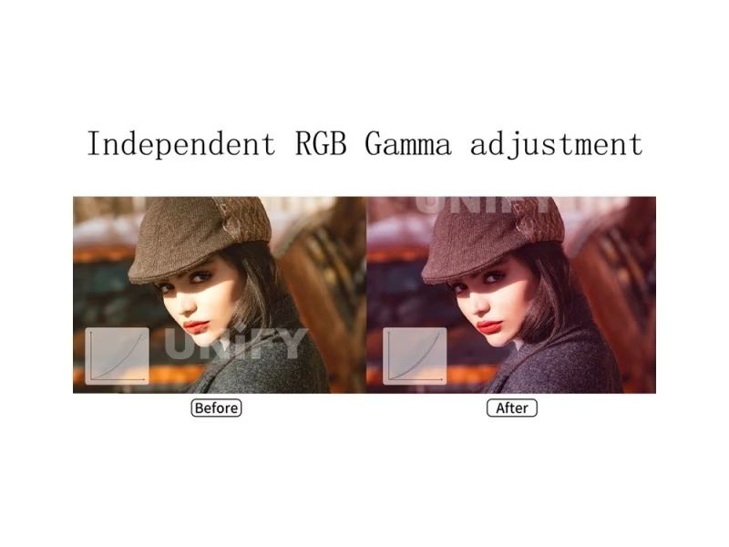
Infi-bit color extension plus 10-bit full-gamma independent RGB adjustment — the card-side color pipeline the HDR signal deserves.
Colorlight’s official HDR comparison:
Colorlight Official — HDR vs normal effect comparison video
How Do 120–240Hz and Low Latency Work on the Colorlight i9 LED Receiver Card?
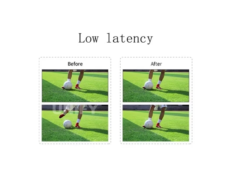
The i9 drives 120–240Hz refresh — the range that removes ghosting and motion blur on camera and in fast-moving content. The condition is the usual one for receiving cards: the module’s driver IC and scan mode set the achievable ceiling, so the refresh claim travels with the parameter file, not alone. The low-latency function adds the second half of the motion story: the card keeps the video path short for latency-sensitive walls, the feature that matters on virtual production volumes and interactive installations.
The color pipeline behind the motion performance: 65,536 grayscale levels with low-brightness enhancement, 10-bit full-gamma independent RGB adjustment, color temperature and gamut control, and seam correction — the display-quality stack that makes the card the choice for fine-pitch walls where every defect shows at close viewing distance.
Colorlight’s official high-end image solution overview:
Colorlight Official — High-Quality Image Solution video
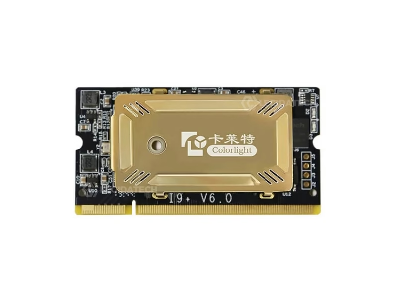
Why Does the SODIMM Format Matter on the Colorlight i9 LED Receiving Card?
The i9 plugs into its DDR2-200 SODIMM socket like a laptop memory module — no screws, no ribbon cables, no mounting hardware. Three engineering consequences follow:
Field replacement in seconds
A failed card swaps like a memory stick — pull, push, done. For rental crews and venue techs, that is a repair measured in seconds instead of a service call.
Thin cabinets stay thin
At 67.6×35.5mm and 9.5g, the card disappears into the HUB board plane — the form factor that lets fine-pitch cabinets keep their slim profile.
Fine-pitch ready by design
The i9’s generation rode the trend of fine-pitch walls replacing LCD spliced walls — the SODIMM card was the receiving side of that transition.
Colorlight’s official fine-pitch trend video:
Colorlight Official — Look One Is Enough fine-pitch trend video
How Does Calibration Work on the Colorlight i9 LED Receiving Card?
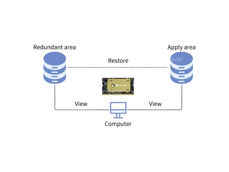
The i9 carries 14-bit point-by-point brightness and chromaticity calibration with color temperature and gamut adjustment — the calibration depth fine-pitch walls need, where module-to-module variation is visible at arm’s length. The card also supports smart modules that store their calibration coefficients and module parameters on the module itself, so a card or module swap re-reads the stored data instead of re-measuring. Firmware redundancy with readback protects the card’s own state the same way.
The verification side of the story: Colorlight’s LEDAnalyzer system measures display quality against industry testing methods — the same discipline a factory applies before shipping a fine-pitch wall, and the reference for what a commissioned i9 wall should measure. OSD, screen rotation, LED point-by-point error detection and cable status monitoring round out the maintenance toolkit.
Colorlight’s official quality-test system:
Colorlight Official — LEDAnalyzer MLED Display Quality Test System video
How Do You Configure the Colorlight i9 LED Receiver Card with iSet?
Five steps from wired card to displaying module, in Colorlight’s iSet software:
Seat the card
Push the SODIMM card into the HUB board socket, connect the sender’s Ethernet to the network port, power the cabinet at DC 3.8–5.5V.
Detect sender and cards
iSet detects the sending device and lists every i9 per port — index, type and cable status.
Load the module parameter file
The module supplier’s file defines driver IC (PWM or Silan), scan mode (up to 64 scan) and data routing (32 parallel or 64 serial groups).
Map the layout and calibrate
Map the receiving card layout, then load the 14-bit calibration coefficients — or read them from smart modules that store their own.
Send, save, verify monitoring
Send and save the parameters, then check the monitoring page — the five power channels, temperature, humidity and fan status should all read live.
Colorlight’s official iSet tutorial:
Colorlight Official — iSet User Guide Beginner’s Tutorial video
Where Is the Colorlight i9 LED Receiving Card Used?
Fine-Pitch Walls
HDR, 65,536 levels, 14-bit calibration and the slim SODIMM form — the card tier where close-viewing defects disappear.
Premium Rental
120–240Hz and low latency for camera-facing stages; dual-card hot backup for shows that cannot fail visibly.
Virtual Production & Broadcast
Low latency and high refresh keep camera-facing volumes clean; HDR10/HLG handle graded content.
Creative & Shaped Screens
64 serial data groups with arbitrary pumping point and data offset — spherical, curved and freeform displays.
Why Buy the Colorlight i9 LED Receiving Card From an LED Display Factory?
The i9’s listing chaos documented above — three loading figures, one of them from a different card — is what happens when hardware moves through unverified channels. Buying through a full-line LED screen manufacturer changes the purchase in three ways:
1. Verified hardware against Specification V1.4.1. Every i9 we ship comes from Colorlight’s authorized channel, is tested on live LED modules before dispatch, and carries serial-number traceability. The first question we answer is the one most listings cannot: which generation — and which card’s loading figure — the quote describes.
2. Commissioning that finishes the fine-pitch layer. Our engineers configure the i9 with iSet end to end — the parameter file, the 64-group mapping, the 14-bit calibration coefficients and the five-channel monitoring verification — against your actual modules. Our quality control of LED display process applies the same rigor to every batch.
3. Lifecycle economics. A 2.5W solid-state card with a −25°C to +75°C operating range has no wear parts — LED screen lifespan is set by the modules, not the card. We back the i9 with a 2-year warranty and keep spares for the project’s operating life.
How Much Does the Colorlight i9 LED Receiving Card Cost?
Price transparency, stated plainly: the i9 is a high-end receiving card with no reliable public street price in the August 2026 listings we reviewed — the few prices attached to it are polluted by the same i9/i9+ confusion that pollutes its specs. We will not invent a number. Factory-direct tiers for B2B buyers:
Ask for a factory-direct quote at your card count — the quote will state the generation (i9, not i9+) and the loading figure it is based on, which is the verification that matters at this tier.
What Do Buyers Ask About the Colorlight i9 LED Receiving Card?
Why Trust the Colorlight i9 LED Receiving Card From UnifyLED?
Every batch ships with Colorlight original packaging, tested on live modules before dispatch.
Ready to Source the Colorlight i9 LED Receiving Card?
Factory-direct pricing, genuine i9 stock with generation stated, iSet commissioning and 2-year warranty.
unifyledscreen@gmail.com | +86-191-18802497
What Should Engineers Know Before Buying the Colorlight i9 LED Receiving Card?
Published: August 2026 | 13 min read | UnifyLED Engineering Team
The Colorlight i9 LED Receiving Card is the high-end of Colorlight’s receiving line — the card tier for fine-pitch walls and premium rental — and the one whose marketplace listings carry three different loading capacities, one of them belonging to a different card. This guide resolves the numbers against the official Specification V1.4.1’s pin definitions, then walks the decisions that matter when a card choice determines what a fine-pitch wall can display.
Short answer: The Colorlight i9 is a 67.6×35.5mm, 9.5g SODIMM receiving card with a 384×256-pixel load, 32 parallel / 64 serial data groups, HDR10 + HLG with 30-bit input, 120–240Hz refresh, 65,536 grayscale levels, 14-bit calibration, and five-channel power monitoring with dual-card hot backup. The i9+ is the newer generation with 256×1024 pixels and 128-scan support. Listings quoting 256×1024 for the i9 are copying the i9+ specification.
Chapter 1 — Definition: The SODIMM Card for Fine Pitch
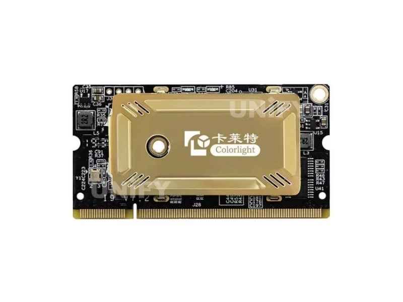
The Colorlight i9 LED Receiving Card is a high-end receiving card built on a DDR2-200 SODIMM connector — it plugs into the HUB board the way a memory module plugs into a laptop. The form factor is the design statement: 67.6×35.5mm and 9.5g, seated flat in the board plane, swappable in seconds. That engineering choice serves the two markets the card was built for — fine-pitch walls where cabinets must stay thin, and premium rental where a failed card must swap between shows, not after them.
The card’s quality stack marks its tier: HDR10 and HLG display with up to 30-bit input, 120–240Hz refresh, 65,536 grayscale levels, 14-bit point-by-point calibration, and 64 serial data groups for the densest module designs. For the receiving card’s role in the chain, the synchronous vs asynchronous LED control guide covers where it sits; for the sending side that feeds it, the LED video processor ladder completes the picture.
The seam-correction and screen-rotation features round out the fine-pitch toolkit: seam correction evens the junction between modules — the defect that reads as a grid on close-viewed walls — and screen rotation supports rotated module orientations in creative layouts. OSD overlays cabinet status directly on the display, and the point-by-point LED error detection flags dead or weak pixels before they spread into visible clusters. On a fine-pitch wall, the small features are the difference between a wall that looks manufactured and one that looks finished.
Chapter 2 — Loading: 384×256 and the Three-Version Problem
The i9’s official loading capacity is 384×256 pixels full color. In August 2026 listings, the same card appeared with two other figures: 512×384, found in a single Chinese specification copy, and 256×1024 — the i9+’s figure, copied onto i9 pages by listing authors working from the wrong sheet. The 256×1024 misattribution matters most: a wall planned against it undercounts cards by a wide margin, and the shortfall appears at installation.
The data-group architecture underneath: 32 parallel RGB groups or 64 serial RGB groups — the latter confirmed by the official pin table, which names DATA1 through DATA64 on the SODIMM connector. Sixty-four serial groups is what lets the i9 drive high-density module designs and freeform layouts with arbitrary pumping points and data offsets. The scan range runs static through 64 scan, and the driver IC support covers mainstream PWM chips plus Silan chips — the chip families fine-pitch modules actually use.
The creative-display capability rides on the same 64 channels: arbitrary pumping points and data offsets let the card route data to modules that sit at odd angles and positions — spherical screens, curved strips, diamond layouts. On a fine-pitch wall, the shaped-screen capability matters more than on any coarser pitch, because the modules themselves are small enough to follow a curve without visible stepping. The i9’s generation was built with both halves of that equation in mind: the channel count for the geometry, and the calibration depth for the finish.
Chapter 3 — i9 vs i9+: The Generation Check
Two generations share the i9 name, and the differences are procurement-critical, in three numbered points:
- Capacity and scan. 384×256 and 64-scan on the i9 versus 256×1024 and 128-scan on the i9+ — the newer platform reshapes the load for ultra-fine-pitch modules.
- Data groups. 64 serial groups on the i9 versus up to 128 on the i9+ — the i9+ drives the highest-density designs.
- Monitoring depth. Both carry five-channel power monitoring; the i9+ adds door, fan and smoke channels through the M3 module.
The production-status confusion on one directory page — “out of production” — is the same story from the other side: the i9+ is the current generation, and the i9 remains available through genuine channels. The verification habit for this product line: ask the supplier to state the generation and the loading figure the quote is based on. A quote that cannot do both is describing hardware the seller has not verified.
Chapter 4 — HDR at the Receiving Card Layer
The i9 supports HDR10 and HLG with up to 30-bit input — and the receiving card is the last device in the chain, which makes card-level HDR the difference between an HDR wall and an SDR wall wearing an HDR sender. The sender processes the extended range; the card renders it — if the card crushes the signal back to standard range, the HDR pipeline died at the last step. On the i9, the range survives: 10-bit content reaches the card untruncated, Infi-bit color extension preserves the gradation, and the 10-bit full-gamma independent RGB adjustment keeps the color response under control.
The practical test for any fine-pitch HDR project: confirm every layer in the chain handles the HDR signal — sender, receiving card and module driver. A single SDR-mapped layer silently undoes the investment, and the receiving card is the layer most often overlooked because most receiving cards do not mention HDR at all.
The HDR story connects directly to the refresh story. 120–240Hz output removes ghosting and motion blur — the artifacts that show worst on fine-pitch walls at close viewing distance — and the low-latency function keeps the video path short for camera-facing volumes. As with every receiving card, the refresh ceiling follows the module’s driver IC and scan mode; the parameter file, not the headline, is the number that counts at commissioning.
Chapter 5 — The Pin Table: What the Official Document Actually Proves
The official i9 Specification V1.4.1 renders its overview pages as images, while the connector pin definitions are fully extractable — and those pin tables are the most trustworthy part of the document, because they name hardware capabilities no listing states. Four facts stand out:
DATA1–DATA64 — sixty-four named data lines, the hardware proof of the 64-serial-group capability. Power_M1–Power_M5 — five voltage-monitoring inputs, a monitoring depth most receiving cards reach only with a multifunction card bolted on. RCV_BK1 + RCV_BK2 — the physical lines of the dual-card hot backup, wired at the connector level. LED_TEMP · LED_HUM · LED_FAN — temperature, humidity and fan sensing on the card, plus UART/I2C and status LEDs for field diagnosis. When a listing’s claims contradict the pin table, the pin table wins — it is the hardware.
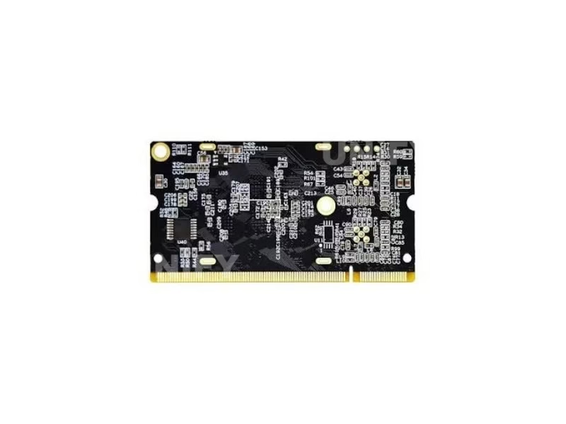
The remaining pin names fill in the daily-operation picture: LED_OE, LED_LAT and LED_SCLK are the display control lines every receiving card carries; the red, green and blue status LEDs plus the FALED_BTN_IND indicator give a technician the first diagnostic read at the cabinet; and the DDR2-200 socket itself — J28 in the pin table — is the mechanical fact behind the SODIMM swap story. A pin table this complete is also the verification tool: every hardware claim on this page traces back to a line in it.
Chapter 6 — Configuration, Calibration and the Smart-Module Workflow
The i9 configures in iSet: detect sender and cards, load the module parameter file (driver IC, scan mode up to 64, data routing), map the layout, load the 14-bit calibration coefficients, send and save. The monitoring page then verifies the hardware the pin table promised — five power channels, temperature, humidity, fan — all reading live.
The smart-module workflow is the maintenance upgrade: modules that store their own calibration coefficients and parameters re-load themselves on a card swap, so a replacement card inherits the calibrated state instead of forcing a fresh calibration pass. Firmware redundancy with readback protects the card’s own state the same way. Combined with LED point-by-point error detection, cable status monitoring and OSD, the i9’s maintenance story is built for walls that run unattended between service windows.
The firmware side deserves its own line for rental operations: firmware redundancy means the card holds two firmware copies and recovers from a bad update instead of bricking — and updates plus calibration coefficient downloads arrive quickly over the same network path the wall uses. On a touring fleet, that is the difference between an update performed in the warehouse and a card shipped back to the factory.
Chapter 7 — Price in 2026: The Honest Answer
The i9 has no reliable public street price in the August 2026 listings we reviewed — the few prices attached to it carry the same i9/i9+ pollution as its specs, and a number built on the wrong generation is a number not worth repeating. The honest procurement approach at this tier: factory-direct quoting by card count, with the generation and loading figure stated on the quote. That is the verification that matters, and it is the difference between a price and a number.
The market context: the LED display control system market reached US$659 million in 2025, projected at a 13.6% CAGR to US$1.59 billion by 2032 (QYResearch, Global LED Display Control System Market Report 2026), with receiving and sending cards the two largest segments. Lifecycle costs favor the card: a 2.5W solid-state design with a −25°C to +75°C operating range has no wear parts, and LED screen lifespan is set by the modules, not the electronics.
Chapter 8 — i9 vs the i5A Sisters: Three Cards, Three Jobs
The Colorlight receiving line now spans three distinct jobs, and the choice is cleaner than the model names suggest. The i5A-905 is the compact sync-only card with the 16,000Hz refresh ceiling — camera-facing walls on a budget. The i5A-F is the dual-mode card with the 2Gbit fallback — walls that must never go black. The i9 is the quality tier: HDR, 120–240Hz, 64 serial groups, five-channel monitoring — fine-pitch and premium rental walls where display quality is the product. None of the three replaces the others; the project’s content plan picks the card.
The decision matrix in one pass: start with downtime tolerance — never-black mandates the i5A-F. Then check camera exposure — flicker-critical walls need the i5A-905’s 16,000Hz or the i9’s 120–240Hz band. Then check content — HDR or 10-bit material points to the i9. Then check pitch — fine-pitch walls with dense module designs need the i9’s 64 serial groups and 14-bit calibration. Most projects land on one card after two questions; the ones that land on the i9 are the ones where the wall itself is the product.
The ecosystem rule closes the decision: the receiving card follows the sending controller, and the Colorlight ladder runs from the X2 through the Z6 PRO-G2. The cross-ecosystem comparison sits on the Novastar MRV412 receiving card page.
Conclusion
The Colorlight i9 LED Receiving Card holds the quality tier of Colorlight’s receiving line for reasons the pin table proves: 64 serial data channels, five monitored power rails, dual-card backup lines and native environment sensing — on a 9.5g SODIMM module that carries HDR10 and HLG to the wall. Specify it with the corrected numbers in hand — 384×256, not the i9+’s 256×1024 — and the generation stated on the quote. Buy it through a verified LED screen manufacturer that tests cards on live modules and commissions the parameter file, calibration coefficients and monitoring verification against your actual wall. Choose it when the wall is fine-pitch, camera-facing or premium rental — and the receiving layer becomes the part of the wall that quietly holds the quality ceiling, which is exactly what it is for.
Which LED Controllers Should You Pair With the Colorlight i9?
The Colorlight receiving ladder and sending side plus Novastar comparisons on UnifyLED.
Novastar & Guides
Where Can You Download Colorlight i9 LED Receiving Card Resources?
Both official documents behind this page — the i9 Specification V1.4.1 and the extension board pin mapping.