
LED Display Signal Cable Troubleshooting: Diagnose Ethernet, Fiber & Flat Cable Faults
Published: 2026-08 | Reading time: 8 min | UnifyLED Engineering Team
A single faulty signal cable can black out an entire section of an LED display — yet LED display signal cable troubleshooting remains the most overlooked skill in the technician’s toolkit. Unlike power failures, which are immediately obvious, signal cable faults masquerade as dead modules, scrambled images, or intermittent flickering. They waste hours of diagnostic time when the fix is often a 30-second cable swap. This guide provides a systematic, field-tested methodology for diagnosing every signal cable type in an LED display system: copper Ethernet, fiber optic, and flat ribbon cables. As a LED screen manufacturer, we train our installation teams on this exact workflow — and now it is yours.
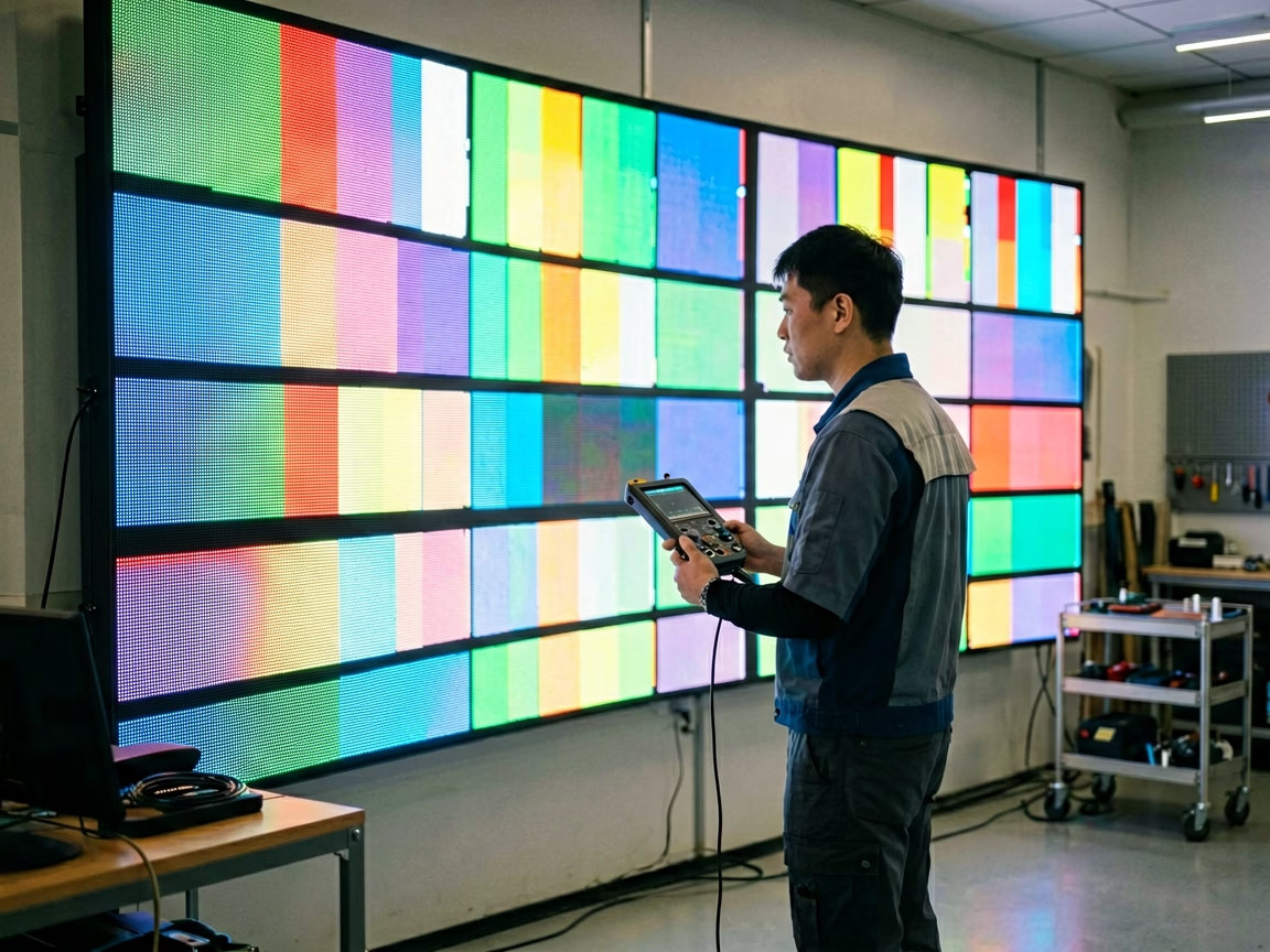
1. What Is the LED Display Signal Cable Chain? Data Flow Explained
Before diagnosing any cable fault, understand the complete path that pixel data travels. The video source — a PC, media server, or camera — outputs a signal via HDMI, DVI, DP, or SDI to the sending controller (such as a NovaStar MCTRL series). The controller packetizes the pixel data and distributes it through 4 to 20 Ethernet output ports. Each port connects to a chain of LED cabinets via Cat5e/Cat6 copper cables. Inside each cabinet, a receiving card accepts the Ethernet data and drives the LED modules through flat ribbon cables (HUB75E or HUB320 connectors). For outdoor installations exceeding 100 meters, fiber optic cables replace copper to overcome signal attenuation.
A fault anywhere in this chain — from the sending controller’s RJ45 port to the last module’s flat cable connector — produces visible display anomalies. The key insight of effective LED display signal cable troubleshooting is that the failure pattern — which cabinets are affected and how — already tells you which cable type is the culprit before you open a single cabinet. For background on the control architecture, see our guide to LED display control system architecture.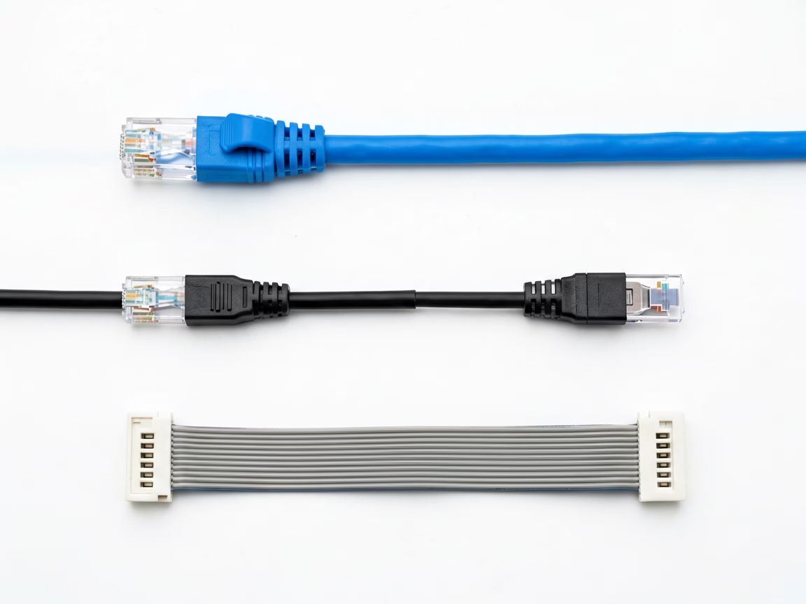
2. How to Diagnose Ethernet Cable Faults in LED Display Signal Cable Troubleshooting
Ethernet cables carry the bulk of pixel data in any LED display system. They are also the cables subjected to the most physical abuse — stepped on, coiled tightly, pulled through conduits, and reconnected hundreds of times in rental deployments. The failure rate of an Ethernet cable in a rental LED environment is approximately 10× higher than in a fixed installation, purely due to handling cycles.
2.1 Common Failure Modes
Broken conductors inside the jacket: The most deceptive failure — the cable looks perfect externally, but one or more of the eight internal conductors has fractured from repeated bending. The cable passes a simple continuity test when lying flat but fails intermittently when moved. This is especially common near the RJ45 connector boot where bending stress concentrates.
Corroded or bent RJ45 pins: Outdoor LED installations expose connectors to humidity, temperature cycling, and in coastal environments, salt spray. Gold-plated contacts resist corrosion but are not immune — a single bent pin on pin 1 or pin 8 (the outermost positions, most vulnerable to mechanical damage) can disable the entire link.
Poorly crimped connectors: A field-crimped RJ45 plug where the insulation displacement contacts did not fully pierce each conductor’s insulation. The cable works initially but degrades within weeks as oxidation develops at the partial connection points.
Length exceeding specification: The 100-meter maximum for copper Ethernet (TIA/EIA-568 standard) is a hard limit, not a guideline. Beyond 100 meters, signal attenuation and crosstalk increase exponentially. A 105-meter cable may work intermittently; a 120-meter cable will not work reliably under any conditions. For reference on cabling standards, see our guide to fiber optic vs Ethernet for LED display.
2.2 Symptom-to-Cause Mapping
All cabinets downstream of a specific cabinet are black: The Ethernet cable feeding that first-failed cabinet is open-circuit or unplugged. Data cannot reach any cabinet beyond the break.
A single cabinet flickers or displays noise: The short jumper cable between this cabinet and the previous one has an intermittent connection. The cabinet is receiving partial data frames, resulting in corrupted pixel output.
Image is offset or scrambled in one section: This is not a cable fault — it is a cabinet connection mapping error. But the symptom is often misdiagnosed as a cable issue, so it belongs in this differential diagnosis. Verify mapping in NovaLCT before replacing cables.
2.3 Diagnostic Procedure
Step 1: Identify the port mapping. In NovaLCT, navigate to Screen Configuration → Port Mapping. Note exactly which Ethernet output port feeds which cabinet chain. The first failing cabinet in each chain is your diagnostic anchor point.
Step 2: Substitute with a known-good cable. Disconnect the suspect cable at both ends and connect a factory-tested cable (keep a 10-meter Cat6 test cable in your toolkit for this purpose). If the display section recovers, the original cable is confirmed faulty — do not reuse it, even if it “looks fine.”
Step 3: Test with a cable tester. An Ethernet continuity tester (approximately $15–40) verifies all 8 conductors are intact and wired to the correct pins (T568B standard for LED display applications). A cable that passes the tester but still fails in the display has an intermittent fault — replace it regardless.
Step 4: Inspect RJ45 connectors. Use a 10× magnifying loupe to examine each connector pin. Look for pins bent downward (not springing back), green or white corrosion deposits, or inadequate crimp depth where the gold contacts have not fully pierced the conductor insulation.
Step 5: Measure cable length. If the run exceeds 100 meters, insert an Ethernet extender or convert to fiber at the midpoint. This is not negotiable — a 110-meter copper Ethernet cable will never be reliable regardless of cable quality.
2.4 Prevention Best Practices
For fixed installations: use shielded Cat6A cable in rigid conduit, with service loops at both ends. For rental deployments: invest in high-flex Ethernet cables with reinforced strain-relief boots, gold-plated contacts, and a minimum bend radius rating of 4× cable diameter. Label both ends of every cable — port number on the controller end, cabinet number on the display end. Coil cables using the over-under method to prevent internal conductor twist damage. A professionally installed system from a qualified LED screen manufacturer includes a detailed cabling diagram with every delivery.
3. Why Do Fiber Optic Cables Fail? LED Display Signal Cable Diagnostics
Fiber optic cables transmit pixel data as modulated light pulses, enabling cable runs of 300 meters to over 10 kilometers — essential for stadium installations, building-to-building links, and any deployment where copper Ethernet exceeds its 100-meter limit. Fiber is immune to electromagnetic interference and ground loops, making it the preferred choice for industrial and outdoor environments. However, fiber introduces its own distinct failure modes that require different diagnostic tools and techniques than copper.
3.1 Copper vs Fiber: When to Use Which
Use copper Ethernet (Cat6/Cat6A) for runs under 80 meters in controlled indoor environments. Advantages: lower cost, field-repairable connectors (RJ45 crimp tool), no SFP modules required, and every technician already owns the diagnostic tools. Use fiber optic for runs over 80 meters, outdoor inter-building links, environments with high EMI (near welding equipment, motors, or radio transmitters), and any installation where a ground potential difference exists between buildings. For a complete comparison, see our fiber optic vs Ethernet LED display guide.
3.2 Failure Modes Unique to Fiber
Broken glass fiber inside intact jacket: Unlike copper, a fiber cable shows zero external signs of internal breakage. A cable bent below its minimum radius (typically 10× the cable diameter) can fracture the glass core while the outer jacket remains visually pristine. The only reliable test is a Visual Fault Locator.
Contaminated connector end faces: A single dust particle on a fiber connector face — invisible to the naked eye — can attenuate the optical signal by 3–10 dB. This is the most common fiber fault and the easiest to prevent: clean every connector face before every mating, including brand-new connectors straight from the factory package.
SFP module failure: The SFP (Small Form-factor Pluggable) transceiver at each end of the fiber link is an active electronic component with a finite lifespan. SFP modules degrade gradually — a module that has operated for 3–4 years in a high-temperature environment may begin producing intermittent bit errors long before it fails completely.
Mode mismatch: Single-mode fiber (SMF, typically yellow jacket, 9/125µm core) and multi-mode fiber (MMF, typically aqua or orange jacket, 50/125µm or 62.5/125µm core) are not interchangeable. A single-mode SFP paired with multi-mode fiber will produce an unreliable link with high optical loss, and vice versa.
3.3 Diagnostic Tools and Procedure
Step 1: Check SFP status LEDs. Most SFP modules have a link indicator LED visible through the cage. No light = no physical connection or failed module. Swap the SFP with a known-good spare of the same type (single-mode or multi-mode, matching wavelength). If the link recovers, discard the failed SFP.
Step 2: Use a Visual Fault Locator (VFL). A VFL — a handheld red laser pen, approximately $30–80 — injects visible 650nm light into the fiber core. At the far end, you should see a bright red dot. If no light emerges: the fiber is broken. If light escapes from a point along the cable jacket: the glass is fractured at that exact point. This is the single most valuable fiber diagnostic tool for LED technicians.
Step 3: Clean both connector end faces. Use an LC or SC one-click cleaner (match the connector type). Insert, press once, remove. This removes 99% of contamination. Never use cotton swabs, compressed air, or clothing — these introduce more contamination than they remove.
Step 4: Verify fiber type compatibility. Check the SFP module label (e.g., “1000BASE-LX” = single-mode, “1000BASE-SX” = multi-mode) against the fiber cable jacket printing. Replace mismatched components.
3.4 Prevention for Fiber Installations
Always install fiber with a service loop — 2–3 meters of extra cable coiled at each end — to allow for future re-termination. Use armored fiber cable for outdoor or direct-burial installations. Clean every connector face before mating, without exception. Keep unmated connectors capped with dust caps. Stock at least two spare SFP modules per type used in your installation. For permanent outdoor links, specify LC/APC (angled physical contact) connectors with lower back reflection rather than LC/UPC (ultra physical contact) connectors.
4. How to Fix Flat Ribbon Cable Faults Inside the LED Display Cabinet
Flat ribbon cables — also called FFC (Flexible Flat Cables) or IDC ribbon cables — connect the receiving card output to each individual LED module. These 16-pin (HUB75E) or 20-pin (HUB320) cables carry low-voltage data and control signals. They are thin, flexible, and the most physically vulnerable cables in the entire signal chain. A flat cable pinched between a module and the cabinet frame during reassembly, or a connector tugged at an angle during module removal, produces pixel-level artifacts that look like module failures but are actually cable faults.
4.1 Connector Types and Orientation
The industry standard for LED module data connections is the HUB75E connector — 16 pins arranged in two rows of 8, with a 2.54mm pin pitch. Some higher-density modules use the HUB320 connector with 20 pins. Pin 1 on the cable is marked by a red stripe on the ribbon edge or a triangle molded into the connector body. Pin 1 must align with the Pin 1 marking on both the receiving card and the module PCB. Reversing the cable orientation will not damage components but will produce a completely garbled display on that module — a useful diagnostic clue.
4.2 Failure Symptoms
Single module solid white/black while neighbors are normal: The flat cable to that module is completely disconnected or the data lines are all broken. Check both ends of the cable before suspecting the module itself.
Specific rows or columns dead on a single module: A damaged conductor within the flat cable — the corresponding data line is open-circuit. This pattern is module-specific and does not affect adjacent modules, which is the key differential from a receiving card fault.
Module displays correct content but at reduced brightness: This is typically a power connector fault, not a data flat cable fault. Check the module’s power connector (separate from the data flat cable) first.
Intermittent module behavior when cabinet is handled or vibrated: Classic loose flat cable connector. The connector is partially seated — making contact at rest but losing connection when the cabinet is moved.
4.3 Diagnostic Procedure
Step 1: Visual check. Examine every flat cable connector. A connector sitting at an angle in its socket — not parallel to the PCB — is not fully seated. Press firmly and evenly until the connector body is flush with the socket. You should feel a distinct click as the retention latch engages.
Step 2: Cross-swap test. Swap the suspect flat cable with the cable from an adjacent working module. If the problem follows the cable — the previously good module now shows the fault — replace the cable. If the problem stays with the same module position regardless of which cable is connected, the fault is on the receiving card output port or the module PCB, not the cable.
Step 3: Conductor inspection. Hold the flat cable up to a bright light. Look for kinks, cracks, or dark spots along the conductor traces. A kinked flat cable where the plastic backing shows a permanent crease has almost certainly fractured one or more internal conductors at that point — replace it.
Step 4: Orientation check. Verify that the red stripe (Pin 1) on the cable aligns with Pin 1 markings on both the receiving card and the module. Reversed connectors are a common mistake after module replacement. For broader module-level diagnostics, see our guide to basic debugging of LED displays.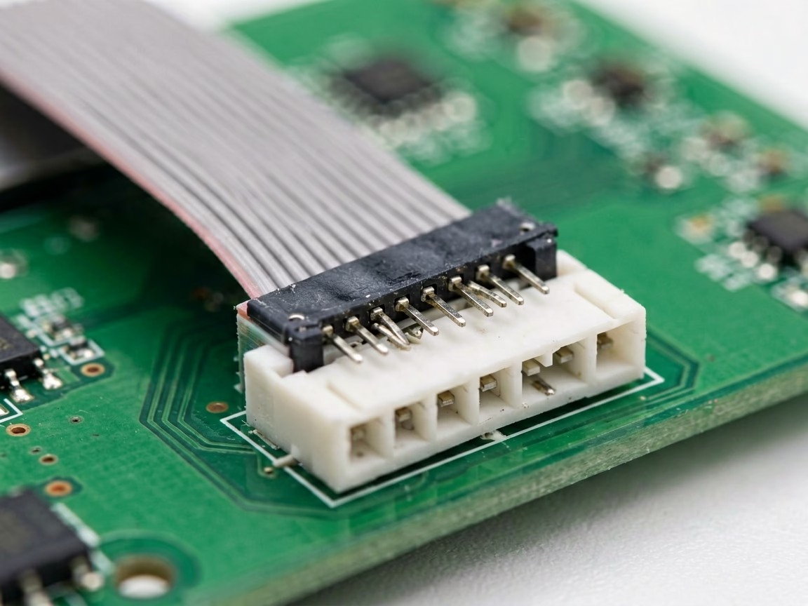
5. When LED Displays Lose Signal: A 6-Step Cable Troubleshooting Workflow
When a display shows signal-related anomalies, resist the urge to start swapping cables randomly. A methodical top-down approach — working from the video source outward through every link in the signal chain — finds the fault faster and prevents introducing new variables. This is the same workflow we use at UnifyLED to train field technicians for LED display configuration and system debugging.
Step 1: Verify the source signal. Connect a known-good monitor directly to the sending controller’s HDMI/DVI loop-through output. If the source image is correct, the problem is downstream of the controller. If incorrect, troubleshoot the source — check the PC graphics settings, resolution, and the cable from the source to the controller.
Step 2: Verify the sending controller output. In NovaLCT, access the screen configuration page. Verify that all ports are correctly mapped. Send a built-in test pattern (color bars, grid, or grayscale ramp) from the controller. If all cabinets display the test pattern correctly, the problem is in the video input path, not the LED system. If some cabinets fail, the problem is in the Ethernet/fiber distribution or receiving cards.
Step 3: Map the failure to the cable topology. Draw a diagram of the cabling pattern — linear chain, Z-shape, or custom. Mark which cabinets are working and which are failing. The first failing cabinet in each chain is the diagnostic focus. The cable feeding it, or the receiving card in the previous cabinet, is the most likely fault location.
Step 4: Isolate by single-cable substitution. Replace one cable at a time with a known-good cable, starting with the cable feeding the first failing cabinet. Observe whether the failure pattern changes. If a single cable swap restores all downstream cabinets, that cable was the sole fault. If the first failing cabinet remains dark with a known-good cable connected, the fault is in that cabinet’s receiving card — not the cable.
Step 5: Check cabinet internals. Open the suspect cabinet. Verify: the receiving card power LED is on, the Ethernet link LED is blinking (indicating data reception), and all internal flat cables are fully seated. A receiving card with power but no link LED activity indicates the Ethernet signal is not reaching the card — backtrack to the previous cabinet’s output or the cable between them.
Step 6: Document and prevent recurrence. Record the fault location, cable type, failure mode, and resolution. Share with the installation or rental team. A preventable cable fault that recurs is a process failure, not a technical failure. For backup and redundancy strategies that minimize single-cable-failure impact, see our guide to LED sending card port backup and LED display system redundancy setup.
6. What Tools Are Needed for LED Display Signal Cable Troubleshooting?
Every LED field technician should carry a signal diagnostic toolkit. These eight items collectively cost under $300 and pay for themselves the first time they prevent an hour of unproductive cable swapping:
1. Ethernet cable tester ($15–40) — Verifies 8-conductor continuity and T568A/B pinout. Accept no substitute: a cable that “looks fine” is not fine until tested.
2. Visual Fault Locator (VFL) ($30–80) — Red laser pen for fiber continuity testing. The single most valuable fiber diagnostic at this price point.
3. LC and SC one-click fiber cleaners ($10–20 each) — Clean every connector, every time.
4. Known-good test cable set — 2m Cat6, 5m Cat6, 10m Cat6, and a 2m LC-LC duplex fiber patch cable. Factory-tested confirmed-good, stored in a protective case, used only for substitution testing.
5. 10× magnifying loupe ($10–20) — For inspecting RJ45 pins, fiber end faces, and flat cable connectors.
6. Spare SFP modules — Matched to your installation (single-mode LC or multi-mode LC). Minimum two spares per type.
7. Spare flat ribbon cables — HUB75E (16-pin) and HUB320 (20-pin), minimum five spares of each type.
8. Laptop with NovaLCT — Pre-installed, pre-configured with a known-good USB-to-Ethernet adapter for direct controller connection. Do not rely on the client’s network for diagnostic access.
For large-scale installations, add an OTDR (Optical Time Domain Reflectometer) at $500–2,000 for precise fiber fault distance measurement, and a network cable certifier that tests full Cat6 bandwidth compliance — not just continuity — for installations where cable performance must be validated to specification. A properly equipped technician from a professional LED screen manufacturer resolves signal cable faults in minutes rather than hours.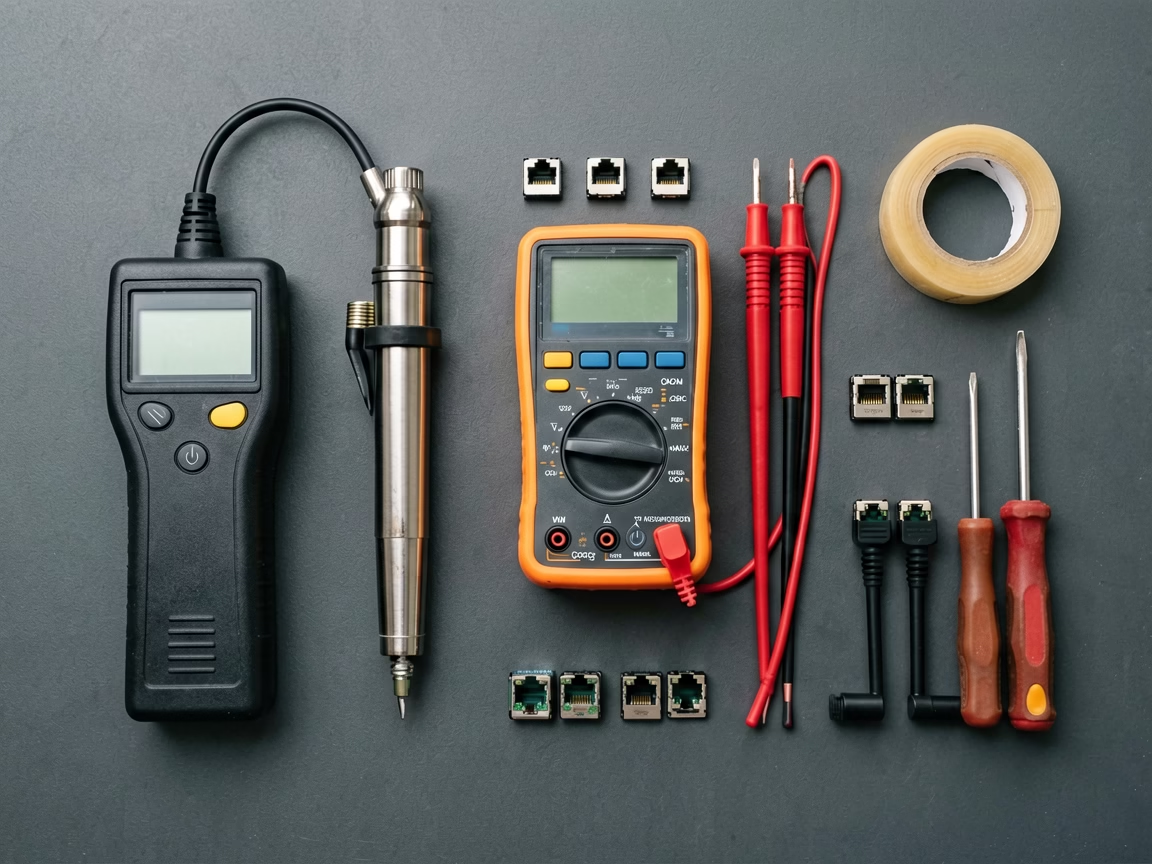
7. How to Master LED Display Signal Cable Troubleshooting: Final Summary
Signal cable faults are not mysterious — they follow predictable patterns that reveal themselves through systematic observation. The technician who masters LED display signal cable troubleshooting stops chasing phantom module failures and starts resolving real problems in the signal path: the Ethernet cable with a broken conductor at the strain relief, the fiber connector contaminated by a single dust particle, the flat cable pinched during module reassembly. These are the faults that cause 80% of signal-related display issues, and each one is diagnosable in minutes with the right workflow and a $300 toolkit.
The six-step top-down method — source → controller → topology → substitution → cabinet internals → documentation — prevents the random cable-swapping chaos that wastes technician hours and fails to identify root causes. Combined with preventive practices — high-flex Ethernet for rental, fiber service loops, flat cable management, and connector cleaning discipline — signal cable faults become rare, predictable, and quickly resolvable rather than recurring sources of downtime. For LED display configuration assistance, LED display configuration and system debugging is available from UnifyLED’s engineering support team.
Need Professional LED Display Technical Support?
Factory-direct LED displays with global delivery. Free technical consultation for troubleshooting, system design, and on-site support planning.
legidatechled@gmail.com | +86-191-18802497