
How to Configure an LED Sending Card: Complete Walkthrough
The sending card is the bridge between your video source and your LED display. Configuring it correctly is the difference between a display that shows exactly what the source outputs and a display that shows nothing at all—or worse, shows a garbled, flickering image that looks like a hardware fault but is purely a software configuration error. This guide provides the complete LED sending card configuration walkthrough for system integrators and commissioning technicians.
As a LED screen manufacturer, we pre-configure sending cards before shipment, but field technicians must understand the process for on-site adjustments. For the broader commissioning context, see our guide to LED display basic debugging. For selecting the correct card, see how to choose a sending card.
What Do You Need Before You Configure an LED Sending Card?
- Install the control software. Nova LCT for NovaStar cards—download the latest version from NovaStar’s website, not from a third-party source. LEDVision for Colorlight cards. The software version must be compatible with the card’s firmware version.
- Connect the sending card to the control PC. Via USB (direct) or Ethernet (network). USB is preferred for initial configuration—it does not require IP address configuration and eliminates network-related detection failures.
- Obtain the correct .rcfg file for the LED modules installed in the display. This file is module-specific—it cannot be guessed, improvised, or borrowed from a similar-looking module. The module manufacturer or LED display supplier provides it.
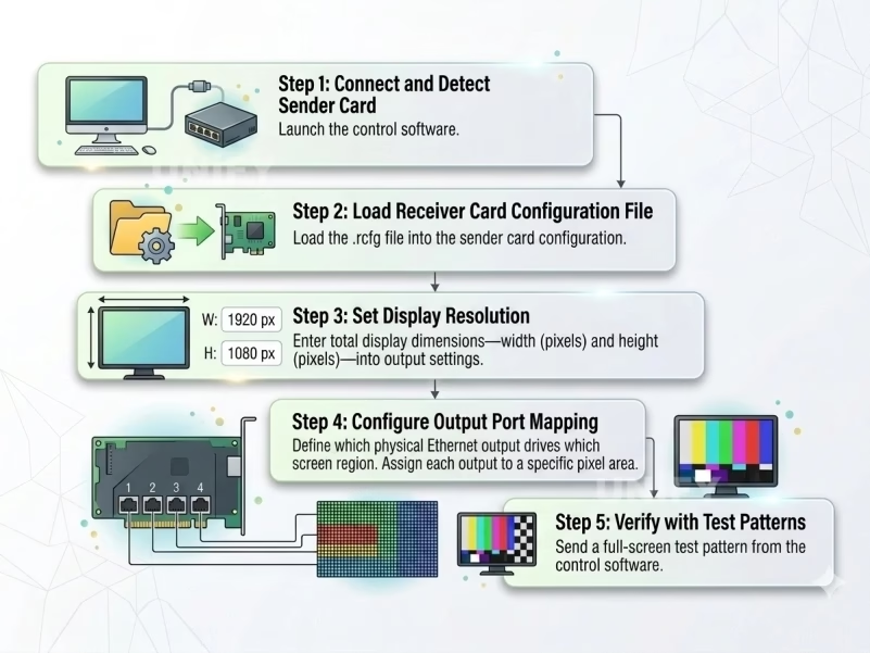
Step-by-Step Configuration
Step 1: Connect and Detect the Sending Card
Launch the control software. If connected via USB, the card should appear automatically in the device list. If connected via Ethernet, you may need to configure the PC’s IP address to the same subnet as the card (default NovaStar IP: 192.168.0.10). Once detected, the software displays the card model, firmware version, and current status.
Step 2: Load the Receiving Card Configuration File
Load the .rcfg file into the sending card’s configuration. This tells the sending card what type of receiving cards and modules are connected. Some systems load the .rcfg directly to each receiving card via the sending card’s Ethernet outputs. Verify that all receiving cards report the loaded configuration as active.
Step 3: Set the Display Resolution
Enter the total pixel dimensions of the display—width and height in pixels—into the sending card’s output settings. This must match the physical pixel count, calculated as: Width (mm) ÷ Pixel Pitch (mm) × Height (mm) ÷ Pixel Pitch (mm). Do not enter a standard resolution (1920×1080) unless that is the display’s actual pixel count. See our resolution calculation guide for the methodology.
Step 4: Configure Output Port Mapping
Define which physical Ethernet output drives which section of the display. Each output is assigned a rectangular region of the total pixel grid. The regions must not overlap, and the total pixels assigned to each output must not exceed that output’s loading capacity (typically 650,000 pixels for standard cards at 8-bit). Load each output evenly—avoid one output at 95% of capacity while another is at 20%. For loading capacity details, see our loading capacity guide.
Step 5: Verify with Test Patterns
Send a full-screen test pattern from the control software. Start with a numbered grid to verify cabinet mapping and output assignment. Then full white, full red, full green, full blue, and a grayscale ramp. If any pattern fails, return to the relevant configuration step—do not proceed with a known problem.
Common Configuration Errors
- Wrong .rcfg file. The most common cause of garbled images. The .rcfg must match the exact module model, not a similar one.
- Resolution mismatch. Entering 1920×1080 for a display that is physically 1600×900 produces a stretched or cropped image.
- Output overload. Assigning more pixels to an Ethernet output than its rated loading capacity. The affected section will not display.
- Firmware-software mismatch. An outdated firmware version on the card may not be fully compatible with the latest software. Update firmware before configuring.
- Saving without verifying. Configuration changes are not automatically saved. Save to the card’s non-volatile memory after verification—otherwise the configuration is lost on the next power cycle.
Frequently Asked Questions
No. The .rcfg file defines how the receiving card interprets pixel data. Without it, the receiving card does not know the module’s pixel dimensions, scan mode, or RGB channel order. You can read back the .rcfg from an already-configured receiving card if the original file is lost, but you cannot configure a new system without one.
Check in this order: (1) Is the card powered on? Verify power indicator LED.
(2) If using USB, try a different USB cable and port.
(3) If using Ethernet, verify the PC’s IP address is on the same subnet as the card.
(4) Check Windows firewall—it may be blocking the control software’s network access.
(5) Try detection from a different PC to isolate whether the problem is the card or the computer.
Conclusion
Configuring an LED sending card is a software procedure with hardware consequences. Every setting entered—resolution, output mapping, configuration file—directly determines what appears on the display. The time to discover a configuration error is during the commissioning test pattern phase, not after the client has signed off on the installation. Verify every setting. Save the configuration. Back it up. A correctly configured sending card is the foundation of every reliable LED display installation.
Email: legidatechled@gmail.com | WhatsApp: +86-191-18802497