- Home
- »
- LED Academy
- »
- LED display maintenance and troubleshooting
LED Display Screen Lifespan and Maintenance
Table of Contents
Factors Affecting the Lifespan of LED Display Screens and Precautions for Use
1. Factors Affecting the Lifespan of LED Display Screens
An LED display screen is a complex device composed of numerous semiconductor, power electronic, and electrical components. It typically adopts a modular or unitized structure. It consists of a display circuit, signal circuit, drive circuit, control circuit, power supply circuit, protection circuit, and cooling fans. Since most LED display circuit boards use SMT (Surface Mount Technology), fault diagnosis is generally limited to finding the faulty unit or module at the unit or board level, due to factors such as detection instruments, technical documentation, and skill level.
Although LED display screens now use many new components and optimized structures, it is still inevitable to use components with a relatively shorter lifespan from the perspective of current component technology and cost-effectiveness. At the same time, the lifespan of components may be shorter than expected due to the influence of the installation environment. The reliability of an LED display screen follows the “bathtub curve” characteristic, as shown in the relationship between the failure rate and usage time in Figure 5-1.
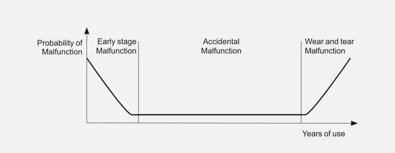
Figure 5-1 Relationship between LED display failure rate and usage time
Early-Stage Failures: These occur during the installation, commissioning, and initial operation stages due to some defect in a component or an external cause. Although components undergo factory testing and the display undergoes rigorous overall testing before leaving the factory, individual components may have hidden defects, and incorrect operations during on-site installation and initial use can lead to a higher failure rate during this period.
Accidental Failures: After the LED display is put into normal use, the number of failures decreases significantly for a long time. These failures may be caused by a sudden failure of an internal component or by a poor use environment, such as water, metal shavings, dust, or humidity entering the display. Since these failures are highly accidental and unpredictable, they are called accidental failures. Generally, the main way to solve accidental failures is to increase the rated margin of components during the design phase and strengthen maintenance during the use phase.
Wear-out Failures: These failures occur near the end of the LED display’s service life, and the main characteristic is that the failure rate increases significantly over time. To extend the lifespan of the display, it is necessary to perform regular inspections and maintenance, and replace components when they are expected to reach the end of their service life.
The main factors affecting the lifespan of an LED display screen are as follows:
(1) Power Supply: The power supply is a major factor affecting the lifespan of the LED display. Its working stability, output voltage, and load capacity will differ under different temperature conditions. Since it plays a crucial role in ensuring energy supply, its reliability directly affects the lifespan of the display.(
(2) Temperature: Theoretically, the ideal operating temperature for an LED display should be around 25°C. However, outdoor LED displays are very sensitive to environmental temperature, which can be complex in applications. The maximum temperature in summer may exceed 60°C, and the minimum temperature in winter may be below -20°C. Under different temperature conditions, the brightness decay values of red, green, and blue LEDs are different. The white balance is normal at 25°C, but at 60°C, the brightness of all three colors decreases, and their decay values are inconsistent. This will cause the overall screen brightness to drop and the color to shift, resulting in a degraded display effect.
(3) Cabinet Design: Cabinet design is very important for an LED display. On the one hand, it protects the circuits, and on the other hand, it provides safety and also has dust-proof and waterproof functions. However, what is more important for the LED display is whether the heat dissipation system design is good. As the display’s power-on time increases and the external temperature rises, the thermal drift of the components also increases, leading to a deterioration in display quality. A good ventilation and heat dissipation design is an essential indicator of cabinet design.
There is a conflict between technology and cost in LED displays. How to ensure the quality of the LED display technically while also reducing costs is a problem that must be paid attention to in the design and application of LED displays. Paying attention to the following technologies is a prerequisite for ensuring the quality of an LED display
(1) Heat Dissipation Performance of the LED Display: If the heat dissipation performance of the LED display is poor, high temperature will affect the stability of the display. In the long run, it will accelerate the performance degradation of the LED display. Therefore, it is necessary to do a good job of heat dissipation design for the PCB inside the LED display and the ventilation and heat dissipation of the cabinet.
(2) Cold Solder Joint Problem: When the LED display does not light up, the most likely situation is that it is caused by cold solder joints. Cold solder joints include many aspects, so it is necessary to pay attention to details and perform strict inspections before leaving the factory.
(3) Verticality of the Through-Hole LED Display: The verticality must be well-controlled. Even a small deviation will directly affect the brightness consistency of the LED display, which will lead to inconsistent color blocks.
(4) LED Mixing: If there is a problem with mixing LEDs of the same color but different brightness bins, it will lead to local differences in brightness on the LED display, which will directly affect the display effect.
(5) LED Electrothermal Value: Under normal circumstances, the maximum current of the LED should not be higher than 80% of the standard value of 20mA. For LED displays with a small pitch, the current value must be reduced.
(6) Drive Circuit Design: If the drive circuit is not well-designed, the LEDs around the edge of the display will be dimmer than those in the middle.
(7) Strictly Control the Temperature and Time of Wave Soldering: The preheating temperature should be 100°C ± 5°C, not exceeding 120°C, and the preheating temperature rise should be smooth. The soldering temperature should be 245°C ± 5°C, and the soldering time should not exceed 3 seconds. After going through the oven, do not vibrate or impact the LEDs until they have returned to normal temperature.
2. Precautions for Using an LED Display Screen
To increase the lifespan of an LED display screen, the following precautions should be taken when using it:
(1) Control Humidity: Operating an LED display in a high-humidity environment can lead to corrosion of the display’s components, which can cause permanent damage. Therefore, you should maintain the humidity of the environment where the LED display is used and prevent moisture from entering the screen.
(2) Proactive Protection: Be proactive in protecting the display. Keep items that may cause damage to the LED display away from it. When cleaning the screen, wipe it as gently as possible to minimize the possibility of damage.
(3) Maintain Stable Power: Keep the power supply stable and ensure proper grounding protection to prevent lightning strikes. Do not use the LED display in severe natural conditions, especially during strong thunderstorms.
(4) Prevent Conductive Materials from Entering the Screen: It is strictly forbidden for water, iron powder, or other conductive metal objects to enter the screen body. The LED display should be installed in a low-dust environment, as large amounts of dust can affect the display effect and damage the circuit. If water enters the display for any reason, the power should be cut off immediately for maintenance until the display board inside the screen is dry before use.
(5) Control Screen Current: When playing content, do not have a full white, red, green, or blue screen for a long time, as this can cause excessive current, excessive heat in the power cord, and damage to the LEDs, which will affect the lifespan of the display.
(6) Control Usage Time: The continuous playback time of an LED display is best not to exceed 12 hours a day. The display should rest for more than 2 hours a day. In the rainy season, the LED display should be used at least once a week. Generally, the display should be turned on at least once a month for more than 2 hours.
(7) Regularly Check Fans: Regularly check if the fans inside the cabinet are working properly. If they are not working, replace them in a timely manner. In rainy weather, check if the screen body is leaking water, and if there are any leaks, repair them in a timely manner.
LED Display Fault Diagnosis Technology and Inspection Methods
1.LED Display Fault Diagnosis Technology and Repair Principles
LED Display Fault Diagnosis TechnologyIn simple terms, “fault diagnosis” for an LED display means finding the faulty components. If you have a batch of different but isolated electronic components, the simple and direct way to find a faulty or unqualified one is to test each one individually. However, if these components have been soldered onto a printed circuit board and are electrically connected, and the total number of components in the circuit is large, it is obviously impossible and unnecessary to desolder and test each component. Generally, the entire circuit is treated as a whole, and through a series of inspections, analyses, tests, and judgments, the faulty component is identified.
The basic steps of LED display fault diagnosis include: inspection, analysis, detection, and judgment. In practice, the purpose of inspection is to lay the foundation for analysis, and the purpose of analysis is to make a judgment. Therefore, fault diagnosis can be considered to include three basic steps: inspection, analysis, and detection. The fault diagnosis process is a cyclical process of inspection, analysis, and detection, gradually approaching the fault point. The fault diagnosis flowchart is shown in Figure 4-1.
2 LED Display Screen Maintenance and Daily Upkeep
In the process of using an LED display, various faults can be caused by factors such as pollution, vibration, heat, and changes in ambient temperature, which can affect the normal use of the display and even cause serious accidents. Therefore, regular maintenance of the LED display can keep it in an optimal operating state and effectively prevent faults, which will have a multiplier effect on the normal operation of the display. Good maintenance of the LED display is crucial for extending its lifespan and ensuring its normal operation.
1. Regular Maintenance of the LED Display Screen
(1) Regular Cleaning: An LED display screen that is exposed to outdoor environments for a long time will inevitably have dust on the screen. It is necessary to regularly clean the screen to keep it clean and tidy, thereby improving the brightness and uniformity of the image.
You can use a cleaning cloth made of superfine fibers, high-purity distilled water, and an antistatic solution to effectively clean dust, fingerprints, and other smudges on the LED display. Alternatively, you can use a brush or a vacuum cleaner to remove dust. Do not wipe it directly with a wet cloth.
(2) Regular Inspection:
Regularly check the firmness of the hanging points of the LED display. If there is any looseness, adjust, reinforce, or replace the hanging parts in a timely manner.
Keep the heat dissipation holes of the screen body unobstructed to maintain convection exchange between the inside and outside of the screen, so that the working temperature and humidity of the LED display are always within the standard range, thereby greatly increasing the lifespan of the display.
Regularly check the wiring for damage and replace severely oxidized or aged power cords in a timely manner to prevent short-circuit faults caused by severe wiring aging. Non-professionals are prohibited from touching the internal wiring of the LED display to avoid electric shock or damage to the wiring. If a fault occurs, it should be repaired by a professional.
Regularly check for damage to the internal electronic components of the LED display. If there is any damage, replace it in a timely manner.
(3) Regular Cleaning: For LED displays with a low protection level, especially outdoor LED displays, dust in the atmosphere can enter the equipment through the ventilation holes, which will accelerate the wear and tear of equipment such as fans and even damage them. Dust can also fall on the surface of the internal controller components, reducing their thermal conductivity and insulation performance. In humid weather, the dust absorbs moisture from the air, which can cause short circuits. It can also cause mold on the PCB and electronic components, leading to a decrease in the technical performance of the equipment and the occurrence of faults. Therefore, the cleaning of the LED display seems simple, but it is actually a very important part of maintenance.
(4) Regular Tightening: An LED display screen is a high-power-consumption device. After running for a period of time, the wiring terminals of the power supply part may become loose and have poor contact due to multiple starts, stops, and hot and cold cycles, forming a “cold solder joint.” In severe cases, they may heat up and even ignite nearby plastic components. The signal wiring terminals may also become loose due to changes in ambient temperature and poor contact due to moisture erosion, which can lead to equipment failure. Therefore, the connectors of the LED display must be tightened regularly. When adjusting the fasteners, you should use even and appropriate force to ensure that they are firm and effective.
2. Maintenance of LED Bad Points (Lost Control Points)
If a single LED is confirmed to be damaged after inspection, you can selectively use the following maintenance methods based on your actual needs.
(1) Front Maintenance: Use a screwdriver of the corresponding model to remove the screws that fix the mask from the front (be sure to keep the screws). Remove the mask and replace the LED. After replacing the LED and sealing it with glue, restore the original mask and tighten the screws (be careful not to press on the LED when screwing). If there is any residual glue on the LED surface, carefully remove it.
(2) Rear Maintenance: Use a screwdriver of the corresponding model to remove the screws from the back (be sure to keep the screws). Unplug the signal cable. For safety, do not unplug the power connection cable to prevent accidents. Carefully remove the module from the sheet metal hole and move it to the back of the cabinet. Then, follow the front maintenance method to replace the LED on a single module.
(3) Replacing the LED: Use a sharp tool (such as tweezers) to remove the glue around the damaged LED and make the LED pins clearly visible. Hold the LED with tweezers in your right hand, and use a soldering iron (the temperature should be about 40°C, as a higher temperature will cause damage to the LED) to contact the solder. Hold it for a short time (no more than 3 seconds; if the time is exceeded but it does not meet the disassembly requirements, you should cool it down and try again) to melt the solder. Use the tweezers to remove the LED. Insert a new LED that meets the requirements into the hole of the PCB correctly (the long pin of the LED is the positive pole, and the short pin is the negative pole; the “square hole” on the PCB is the jack for the positive pin of the LED, and the “round hole” is the jack for the negative pin of the LED). Melt a small amount of solder wire, stick it to the tip of the soldering iron, and use the tweezers to adjust the direction of the LED to make it stable. Solder the solder to the connection between the LED and the PCB, and seal the LED with the same type of glue (pH=7).
The methods for checking if an LED is damaged with a multimeter are as follows:
(1) Set the multimeter to the resistance range R×100. Short the two probes of the multimeter and adjust the ohm zero position. Then, connect the black probe to the positive pole of the LED and the red probe to the negative pole to measure the reverse resistance of the LED. If the measured LED has no resistance, it is good. If it has resistance, it is faulty.
(2) Set the multimeter to the diode measurement range. Connect the red probe of the multimeter directly to the positive pole of the LED and the black probe to the negative pole. If the measured LED lights up, it is normal. If the measured LED does not light up, it is damaged.
LED Display Screen Fault Inspection Methods
1. Intuitive Method
The intuitive method means finding and analyzing faults based on the external symptoms of the LED display without using any instruments. Direct observation includes both powering-off and powering-on inspections. In maintenance, a powering-off inspection should be performed first. Use human senses (eyes, ears, hands, nose) to check for phenomena such as:
Loose plugs or poor contact
Cold solder joints or detached solder
Open circuits or short circuits
Component corrosion, scorching, or discoloration
A blown fuse
The intuitive method is the most basic and simplest method. By observing and checking for various abnormal phenomena like light, sound, and smell that occur during a fault, the maintenance personnel can narrow down the fault to a specific module or even a single printed circuit board. However, it requires the maintenance personnel to have rich practical experience.
Before performing an intuitive inspection, you should ask the on-site personnel about the situation, including the external symptoms of the fault, the approximate location, and the environmental conditions when the fault occurred (e.g., whether there were abnormal gases, open flames, heat sources near the screen, corrosive gases, water leaks, or if someone had previously repaired it).
The implementation of the intuitive method should follow the principle of “simple first, then complex” and “outside first, then inside.” In practice, the first step is to accurately identify the shape, name, representative letter, circuit symbol, and function of all kinds of electronic components inside the LED display. The intuitive method for inspection is mainly divided into the following three steps:
(1) LED display appearance inspection. Check the appearance of the LED display for any signs of collision and whether the external wiring is damaged.
(2) LED display internal inspection. Observe the circuit board and various devices inside the screen.
Check if the fuse is blown.
Check if any components are touching, have broken wires, or if resistors are scorched or discolored.
Check if electrolytic capacitors are leaking, bulging, or deformed.
Check if the copper foil and solder joints on the printed circuit board are in good condition and if there are any signs of previous repairs. When inspecting the inside, you can move some components and parts by hand to check them thoroughly.
(3) Inspection after powering on.
Eyes: Look for sparks or smoke inside the display.
Ears: Listen for any abnormal sounds.
Nose: Smell for any scorched odor.
Hands: Feel if any transistors or integrated circuits are hot to the touch. If there is abnormal heat, you should turn off the power immediately.
The intuitive method is very simple and does not require other instruments. It is very effective for general and damage-related faults. Its effectiveness is strongly correlated with the technician’s experience, theoretical knowledge, and professional skills. The intuitive inspection method requires continuous accumulation of experience through a large number of practical repairs to be used proficiently. This method is often used throughout the entire repair process and is more effective when used in conjunction with other detection methods.
2. Comparison Method
The comparison method is a technique for finding the cause of a fault by comparing the characteristics of a faulty circuit with the correct characteristics. When a certain circuit is suspected, its parameters can be compared with the parameters of a normal circuit in the same working state (or with theoretically analyzed current, voltage, and waveform values). This method is most suitable when a circuit diagram is not available. During maintenance, you can compare the measured data with the drawings, documentation, and normal parameters recorded during normal operation to determine the fault. For LED displays with no documentation or recorded normal parameters, you can compare them with a good LED display of the same model to find abnormal situations in the circuit, and then analyze the cause and determine the fault point. The comparison can be an analogy of identical circuits within the same screen or a comparison between a faulty circuit board and a known good one, which helps the technician quickly narrow down the fault inspection range.
3. Replacement Method
The replacement method is a diagnostic technique for judging a fault by replacing a suspected and difficult-to-measure electrical component or circuit board on the faulty LED display with a new one of the same specification and good performance. Sometimes, when a fault is more hidden, the cause is not easy to determine, or the inspection time is too long, you can use a good component of the same model to replace it to narrow the fault range and further find the fault. This also confirms whether the fault was caused by that component. When using the replacement method, you should note that after removing the suspected faulty component or circuit board, you must carefully check its peripheral circuits. You should only replace it with a new component or circuit board if you are certain that the fault was caused by the component or board itself, to avoid damaging the new part.
Additionally, when the fault status of certain components (such as a capacitor with reduced capacity or leakage) cannot be determined with a multimeter, you should replace it with a new component or connect a good component in parallel to see if the fault changes. If a capacitor is suspected of having poor insulation or a short circuit, one end needs to be unsoldered for testing. When replacing a component, the new component should be of the same model and specification as the damaged one whenever possible.
When the fault analysis concludes that the problem is on a specific printed circuit board, it can be very difficult to pinpoint the fault to a specific area or component due to increasing circuit integration. To shorten the inspection time, you can first replace the board with a spare if available, and then inspect and repair the faulty board later. When replacing a spare board, you should pay attention to the following issues:
(1) Replacement of any spare part must be done with the power off. (2) Many printed circuit boards have switches or shorting jumpers to match specific needs. Therefore, when replacing a spare board, you must record the switch positions and settings on the original board and set the new board in the same way, otherwise, it will cause an alarm and fail to work properly. (3) The replacement of some printed circuit boards also requires specific operations afterward to complete the establishment of software and parameters. This requires carefully reading the user manual for the corresponding circuit board. (4) Some printed circuit boards should not be pulled out easily, such as boards containing working memory or backup batteries, as they may lose useful parameters or programs. If they must be replaced, you must follow the relevant instructions.
Using a spare board of the same model to confirm a fault is a very effective way to narrow the inspection range. If the control board of an LED display has a problem, there is often no other way but to replace it, because most users will not have the schematic diagram and layout, making it difficult to perform chip-level repairs.
Given the above conditions, before pulling out the old circuit board and replacing it with a new one, you must carefully read the relevant information, understand the requirements and operation steps, and then proceed, to avoid causing a bigger fault. The replacement method is highly accurate in determining the cause of a fault, but it can be cumbersome and sometimes difficult to operate, and may cause some damage to the circuit board. Therefore, the use of the replacement method should be based on the specific situation of the LED display fault, as well as the technician’s existing spare parts and the difficulty of replacement. In the process of replacing electrical components or circuit boards, the connections must be correct and reliable, and you must not damage other surrounding components, in order to correctly judge the fault, improve the repair speed, and avoid causing man-made faults.
In the repair of LED display faults, if a two-pin component is suspected of being an open circuit, you may not need to remove it. Instead, you can solder a component of the same specification on top of its pins. If the fault disappears after soldering, it proves that the suspected component was an open circuit, and you can then cut off the faulty component. When a capacitor’s capacity is suspected to have decreased, you can also judge it by connecting a new one in parallel. The precautions for using the replacement method are as follows:
(1) Do not use the replacement method extensively, as this will not only fail to repair the faulty LED display but may even expand the scope of the fault. (2) The replacement method is generally only used after other detection methods have been applied and a component is highly suspected. (3) When the component to be replaced is at the bottom of the board, use the replacement method with caution. If you must use it, you should fully disassemble the screen to expose the component and have enough operating space for replacement.
4. Plug-and-Pull Method
The method of finding a fault by “inserting” or “pulling out” functional circuit board plugins, although simple, is a common and effective method that can quickly find the cause of a fault. The specific steps are as follows:
(1) First, pull out all plug-in boards that are connected to the faulty LED display and all auxiliary circuits. Then, turn on the power switch. If the fault still occurs, you should carefully check the main circuit and the motherboard for faults. (2) If the fault disappears, carefully check each plug-in board for any collisions or short circuits (e.g., touching wires, shorting, touching pins). If there are any, eliminate them. If not, plug in the first board and check again. Continue this process with the remaining boards until you find the faulty plug-in board. Then, based on the fault phenomenon and nature, you can determine which integrated circuit or electronic component is damaged. This way, you can quickly find which plug-in board has a fault.
5. System Self-Diagnosis Method
This method fully utilizes the self-diagnosis function of the LED display. Based on the displayed fault information and the indicators of devices such as light-emitting diodes, you can determine the general cause of the fault. By further utilizing the system’s self-diagnosis function, you can also display the status of various interface signals of the LED display, and find the general location of the fault. It is one of the most common and effective methods in the fault diagnosis process.
All LED displays give fault indications in different ways, which is very important information for technicians. Usually, the LED display will give corresponding fault information for faults related to voltage, current, temperature, and communication.
6. Parameter Inspection Method
LED display parameters are a prerequisite for its normal operation and directly affect its performance. Parameters are usually stored in the system memory. Once the battery is low or the system is interfered with by external factors, some parameters may be lost or changed, preventing the LED display from working properly. By checking and adjusting the parameters, you can sometimes quickly eliminate a fault. This is especially true for LED displays that have been unused for a long time, where parameter loss often occurs. Therefore, checking and restoring the LED display parameters is one of the effective methods in maintenance. In addition, after an LED display has been running for a long time, the performance of electrical components may change, and the relevant parameters may need to be re-adjusted.
LED displays are set with many modifiable parameters to suit different applications and operating conditions. These parameters not only match the system to the specific LED display but are also necessary to optimize all its functions. Therefore, any change (especially in analog parameters) or loss of parameters is not allowed. However, the change in the electrical performance of components caused by the long-term operation of the LED display will break the initial matching and optimal state, which requires re-adjusting one or more related parameters. This method requires a high level of expertise from the technician, who must not only be very familiar with the main parameters of the specific system but also have rich experience in debugging LED display systems.
7. Open-Circuit Method
The open-circuit method is a way to find a fault by manually unsoldering a certain branch or a lead of a component in the circuit. It is sometimes called the “cut-off method.” It is an effective method to quickly narrow down the fault range. You can cut off a certain circuit or unsolder the wiring of a component to compress the fault range. For example, if the current in an LED display’s power supply circuit is too large, you can gradually disconnect suspicious parts of the circuit. The level where the current returns to normal is where the fault lies. This method is often used to repair faults with excessive current and blown fuses.
If you encounter a short circuit or ground fault that is difficult to check, you can replace the old fuse with a new one and gradually or selectively connect each branch to the power supply one by one to test again. When you connect a certain circuit and the new fuse blows again, the fault is in the circuit you just connected and its electrical components.
For multi-branch interconnected circuits, you should selectively disconnect the circuit at a certain point, then power it on and test. If the fuse no longer blows, the fault is in the circuit you just disconnected. Then, you can divide this branch into several segments and connect them to the circuit one by one. When you connect a certain segment and the fuse blows again, the fault is in this segment and a certain component. This method is simple, but it can easily burn out electrical components that were not severely damaged.
8. Short-Circuit Method
LED display faults can be roughly summarized as short circuits, overloads, open circuits, grounds, wiring errors, faults in the peripheral circuits of the LED display, etc. Among these faults, open circuits are more common. They include broken wires, poor connections, loose connections, poor contact, cold solder joints, false solder joints, blown fuses, etc. For this type of fault, in addition to using the resistance method and voltage method, a simpler and more reliable method is the short-circuit method. The short-circuit method uses a well-insulated wire to short-circuit the suspected open-circuit part. If the circuit works normally after a short-circuit at a certain point, it indicates that there is an open circuit at that point. When applying the short-circuit method, you can directly short-circuit to ground for low potential points. For high potential points, you should use an AC short-circuit, which is to short-circuit to ground with an electrolytic capacitor of 20 μF or more, to ensure that the DC high potential does not change. The short-circuit method cannot be used on power supply circuits at will. The short-circuit method is essentially a special kind of circuit division method.
9. Instrument Measurement and Comparison Method
This method uses conventional electrical instruments to measure various AC and DC power supply voltages and pulse signals to find the component causing the fault. For example, you can use a multimeter to check the working condition of each power supply and measure the related signal status measurement points on some circuit boards. You can use an oscilloscope to observe the amplitude and phase of related pulse signals. This method is relatively simple and direct. Based on the fault phenomenon, you can generally determine the location of the fault, and with the help of some measuring tools, you can further determine the cause of the fault and help analyze and judge it.
When LED display printed circuit boards are manufactured, they are equipped with test terminals for convenient adjustment and maintenance. Technicians can use these test terminals to measure and compare the differences in voltage or waveform between a normal printed circuit board and a faulty one, and then analyze and judge the cause and location of the fault. When repairing an LED display, the measurement and comparison method can sometimes also correct “faults” caused by improper adjustment and settings on a circuit board that has been repaired.
The prerequisite for using the measurement and comparison method is that the technician should know the normal voltage values, correct waveforms, and other data for the key parts and fault-prone parts of a normal printed circuit board in order to perform a comparison and analysis. This data should be recorded at all times and accumulated as documentation. Common measurement and comparison methods are as follows:
(1) Voltage Measurement and Comparison Method. This is a detection method for judging faults by measuring the working voltage of electronic circuits or components and comparing them with normal values. The voltages that are frequently tested are the power supply voltage of each stage, the voltage of each pole of a transistor, and the voltage of each pin of an integrated circuit. Generally speaking, the measured voltage results are an important basis for judging whether the LED display’s working status is normal. The part where the voltage deviates significantly from the normal value is often the location of the fault. The voltage measurement and comparison method can be divided into DC voltage detection and AC voltage detection.
AC voltage detection. In LED display circuits, since there are fewer AC circuits, the circuits are relatively simple, and the measurement is easier. You can generally use the AC voltage range of a multimeter to measure from the power input of the LED display. If it is normal, then check whether the AC terminal voltage of the switching power supply is normal to determine the fault location of the front-end power supply.
DC voltage detection. For DC voltage detection, first check the output of the switching power supply circuit. Based on the high or low voltage measured at the input and output terminals, you can further determine which part of the circuit or which component has a fault. When measuring the voltage of a unit circuit, you should first measure the power supply circuit of that unit. Usually, a voltage that is too high or too low indicates that there is a fault in the circuit. When using the DC voltage method to detect the working voltage of each pin of an integrated circuit, you should compare the measured value with the data provided in the repair documentation to determine whether the IC is good or bad.
You can usually measure AC and DC voltage directly with a multimeter, but you must pay attention to the selection of the range and gear of the multimeter. Voltage measurement is a parallel measurement. During the measurement process, you must be focused to avoid short-circuiting two solder joints with the probes.
(2) Current Measurement and Comparison Method. This is a repair method for judging an LED display fault by detecting the working current of transistors, integrated circuits, the current of each local circuit, and the load current of the power supply. When using the current method to detect electronic circuits, you can quickly find the cause of a transistor or electrical component overheating. It is also a common method for detecting the working state of an integrated circuit. When using the current method, you often need to disconnect the circuit and connect the multimeter in series with the circuit. Since this step is more difficult to implement, there are two types of current detection: direct measurement and indirect measurement.
Indirect current measurement is actually using the measured voltage to calculate the current or using a special method to estimate the current. For example, if you want to measure the current of a certain pole of a transistor, you can calculate the current value by measuring the voltage drop across the series resistor on its collector or emitter. The advantage of this method is that you don’t need to create a measurement port on the printed circuit board. In addition, some electrical appliances have temperature-fused resistors on key circuits. By measuring the voltage drop across this type of resistor and applying Ohm’s law, you can estimate the load current in each circuit. If a temperature-fused resistor in a certain circuit is burned out, you can directly measure the current with the multimeter’s current range to determine the cause of the fault.
When an LED display’s fuse blows or a local circuit has a short circuit, the current method is very effective. Current is a series measurement, while voltage is a parallel measurement. In practice, the voltage method is often used first, and the current method is only used when necessary.
(3) Resistance Measurement and Comparison Method. This is a method for judging faults by measuring the resistance of a component to ground or its own resistance. It is effective for repairing open-circuit and short-circuit faults and for determining faulty components. By measuring the resistance of resistors, capacitors, inductors, coils, transistors, and integrated circuits, you can determine the specific location of the fault.
The resistance measurement and comparison method is one of the most basic methods for repairing faults. Generally, there are two methods: “in-circuit” resistance measurement and “out-of-circuit” measurement. When measuring resistance “in-circuit,” since the component being measured is connected to the entire circuit, the resistance value measured by the multimeter is affected by other parallel branches, which should be considered when analyzing the test results to avoid misjudgment. The measured resistance value will be equal to or less than the actual marked resistance value of the component. If it is greater, the component being measured is faulty.
When measuring resistance “out-of-circuit,” you need to unsolder one end of the component or the entire component from the printed circuit board, and then use a multimeter to measure the resistance of the component. This method is more cumbersome to operate, but the measurement results are accurate and reliable.
When using the resistance measurement and comparison method, you should generally test the in-circuit resistance first. After measuring the resistance of each component, you should swap the red and black probes of the multimeter and test the resistance again. This can eliminate the interference of the circuit on the measurement results. You should analyze the results of the two measured resistance values. For a highly suspected component, you can unsolder one end to further test it. In-circuit testing must be done with the power off, otherwise, the measured results will be inaccurate and the multimeter may be damaged. When detecting some integrated circuits that are powered by low voltage (such as 5V, 3V), do not use the R×10k range of the multimeter to avoid damaging the integrated circuit.
There are a few points to pay attention to when applying the resistance measurement and comparison method in practice:
Pay attention to the common “ground” in the detection. To ensure the normal progress of maintenance, the detection instrument and the LED display being repaired must have a common “ground” point.
Pay attention to the high-voltage “series point series line” phenomenon. A faulty LED display often has insulation breakdown, which causes high voltage to string through points and lines, endangering personal safety, damaging measuring instruments, and affecting measurement data. This should be paid attention to.
Follow the repair procedure of “power off before measuring, connect after disconnecting.” Especially for high-voltage measurement, you should first cut off the power supply. To prevent electric shock from the charge stored in large-capacity capacitors, you should discharge them fully before connecting the test leads to ensure personal safety.
The test leads must have good insulation.
Before testing, you must have a full understanding of the detection instrument and the principle of the circuit being tested.
10. Waveform Method
The waveform method is a repair method that uses an oscilloscope to track and observe the changes in the signal at each test point of a signal circuit. It judges a fault based on the presence, size, and distortion of the waveform. The characteristics of the waveform method are that it is intuitive, fast, and effective. An oscilloscope can directly display the signal waveform and measure the instantaneous value of the signal. Some advanced oscilloscopes also have the function of measuring electronic components, which provides a very convenient means of detection. Do not use an oscilloscope to measure high-voltage or high-amplitude pulse parts. When an oscilloscope is connected to a circuit, you should pay attention to the bypass effect of its input impedance. High-impedance, low-input capacitance probes are usually used, and the shell and ground terminal of the oscilloscope should be well-grounded during measurement.
Usually, the schematics of LED displays are marked with clear waveform diagrams at the test locations. These waveform diagrams are an important basis for the waveform method. The waveform method uses measuring instruments to observe the waveform, amplitude, frequency, and position characteristics in the circuit, and can also observe various phenomena such as parasitic oscillations and parasitic modulations. The waveform method is a very effective method for finding, discovering, and eliminating faults, especially for difficult faults. It is very convenient to use this method. The waveform method is also called the dynamic observation method. This method is a detection method when the circuit is in a working state, so you must pay attention to safety during operation.
When using the waveform method for maintenance, there are two types of test instruments commonly used. One is an oscilloscope, which can observe the pulse width, amplitude, period of pulses, the ripple voltage of a stable power supply, and the output waveform of an audio amplifier. The second is a frequency characteristic tester, also known as a sweep frequency generator, which can be used to detect the frequency characteristics, bandwidth, circuit gain, and absorption characteristics of a filter network of various circuits.
11. State Analysis Method
When an LED display fails, the method of analyzing the fault based on the state of the LED display is called the state analysis method. The operation of an LED display can always be decomposed into several continuous stages, which can also be called states. The fault of an LED display always occurs in a certain state, and in this state, what state are the various unit circuits and electrical components in? This is an important basis for analyzing the fault. The more detailed the state division, the more favorable it is for analyzing and judging the fault. When troubleshooting, you must clearly distinguish between various working states, and analyze the working state of each unit circuit and electrical component to find the cause of the fault.
12. Circuit Division Method
The circuit division method is a detection method that separates the circuit involved in a fault from the total circuit. Through detection, you confirm one part and deny another part, narrowing down the fault range step by step until the fault location is isolated.
A complex circuit is always composed of several circuits, and each circuit has a specific function. A fault means the loss of a certain function in that unit circuit, so a fault always occurs in one or more unit circuits. Dividing the circuit actually simplifies the circuit and narrows the fault search range, making it easier to find the fault.
The division method is more convenient to apply to circuits composed of multiple modules, circuit boards, and plug-in connectors. For example, if the fuse in the power supply circuit of an LED display is blown, it indicates that the load current is too large, and the power supply output voltage drops. To determine the cause of the fault, you can connect an ammeter in series at the fuse, and then use the division method to separate the suspected part of the circuit from the total circuit. At this time, you observe the change in the total current. If the current drops to a normal value after a certain part of the circuit is separated, it indicates that the fault is in the separated circuit. There are different division methods, such as the bisection method, characteristic point division method, empirical division method, and point-by-point division method.
The division method is based on a person’s experience to estimate which unit circuit a fault has occurred in, and the input and output terminals of that unit circuit are used as division points. Point-by-point division means to divide the circuit level by level according to the signal transmission sequence, from front to back or from back to front. When using the division method to detect a circuit, you must be careful and pay attention to circuits that cannot be disconnected at will, otherwise, you may not eliminate the fault and may even cause a new one. Strictly speaking, the division method is not an independent detection method, but must be used in conjunction with other detection methods to improve maintenance efficiency.
13. Temperature Increase Method
The temperature increase method is a method to help find faults by artificially increasing the ambient temperature or the temperature of a local component (a hairdryer can be used to increase the ambient temperature of a local component, but be careful not to raise the temperature too high and burn out a component that is working normally). You can heat the suspicious component to accelerate the occurrence of faults in components with poor high-temperature parameters. Sometimes an LED display will fail after working for a long time or when the ambient temperature rises, but it is normal when you turn it off and check it. Then it fails again after working for a period of time. In this case, you can use the “temperature increase method” to check it.
Some LED displays are often normal when they are first turned on, but they fail after a short time, ranging from a few minutes to an hour or two. This is often caused by the poor thermal stability of individual components inside the LED display. Because this type of fault is not fixed, in the repair process, you usually need to make a rough judgment on the fault location based on your experience and the characteristics of the fault phenomenon. You can use a soldering iron or a light bulb to heat the components in the suspicious area. For example, you can use a 20W soldering iron and hold the tip about 1cm away from the suspicious component to heat it locally. If the fault phenomenon reappears immediately when a certain component is heated, you can immediately determine that the fault was caused by the poor thermal stability of that component. The order of heating is transistors, integrated circuits, then capacitors and resistors.
Heating usually has two meanings. One is to accelerate the damage of the component so that the fault appears as soon as possible. The second is to use heating to directly eliminate the fault caused by the circuit board being damp. The opposite method of heating is the cooling method, which is usually used in combination with the heating method. The simplest method is to use cotton dipped in alcohol and apply it to a suspicious component when the LED display fails to cool it down. If the fault disappears when a certain component is cooled, then this component is the faulty one. The cooling method is especially suitable for LED displays that are normal when they are first turned on but fail after a period of use.
14. Tapping Method
The tapping method uses the handle of a small screwdriver or a wooden hammer to gently tap a certain place on the circuit board and observe the situation to determine the fault location (note: high-voltage parts are generally not easy to tap). This method is especially suitable for checking for cold solder joints and poor connections. An LED display is composed of various circuit boards and modules with connectors. Each circuit board has many solder joints, and any cold solder joint or poor connection can cause a fault. After opening the LED display, use an insulated rubber rod to tap the suspicious parts. If the fault of the LED display disappears or reappears, the problem is very likely there.
15. Logical Reasoning and Analysis Method
The logical reasoning and analysis method is a method of analyzing and reasoning from the outside to the inside, tracing the origin, and analyzing and reasoning layer by layer based on the fault phenomenon of the LED display. The various components and functions of the LED display have internal connections. For example, signal transmission, current flow, and voltage distribution all have their own specific laws. Therefore, the failure of a certain part, component, or element will inevitably affect other parts, showing a unique fault phenomenon. When analyzing a fault, you often need to connect this fault to the impact on other parts or find the root cause of the fault from a certain fault phenomenon. This process is a process of logical reasoning. The logical reasoning and analysis method is divided into forward reasoning and reverse reasoning. The forward reasoning method generally analyzes and finds faults from the peripheral circuits, power supply, control circuit, power circuit, and signal circuit based on the fault phenomenon. The reverse reasoning method uses the opposite order to analyze and find faults.
Using the logical reasoning and analysis method to make a specific analysis of the fault phenomenon, and to delineate the suspicious range, can improve the targeting of maintenance and achieve the effect of judging faults quickly and accurately. When analyzing the circuit, you should start with the main circuit, understand the relationship between each unit circuit, and combine the fault phenomenon with the working principle of the circuit to perform a careful analysis and elimination. This can quickly determine the possible range of the fault. When the suspicious range of the fault is large, you don’t have to check level by level in a stepwise manner. At this time, you can check the middle link of the fault range to determine which part the fault occurred in, thereby narrowing the fault range and improving the repair speed.
16. Principle Analysis Method
The principle analysis method is the most fundamental method for troubleshooting. When other inspection methods are difficult to be effective, you can start from the basic principle of the circuit, and check it step by step to finally find the cause of the fault. Using this method requires a clear understanding of the principle of the circuit and mastery of the logic level and characteristic parameters (such as voltage value and waveform) of each point at each moment. Then, you can use a multimeter and an oscilloscope to measure, compare with the normal situation, analyze and judge the cause of the fault, narrow the fault range, and finally find the fault. Using this method requires the technician to have a high level of expertise and a clear and in-depth understanding of the entire system or each part of the circuit.
In general, to inspect a faulty LED display, you should go from the outside to the inside, from the surface to the inside, from static to dynamic, and from the main circuit to the control circuit, and then to the signal circuit. Although there are many methods for inspecting LED display faults, which inspection method is more effective in actual repair depends on the specific situation of the fault.
When repairing an LED display, you usually use the intuitive method first. Some typical faults can often be solved in one go with the intuitive method. For more hidden faults, you can use the oscilloscope method. For faults that are not easy to test, you often use the replacement method, short-circuit method, and division method. The application of these methods can often compress the fault to a smaller range, thereby improving the efficiency of the maintenance work. It must be emphasized that each detection method can be used to detect and judge a variety of faults, and the same fault can also be repaired with a variety of detection methods. During maintenance, you should flexibly apply various detection methods to ensure that the detection work achieves twice the result with half the effort.
After finding the fault point of the LED display, you should start the repair, trial run, and recording, and then hand it over for use. However, you must pay attention to the following matters:
- (1) When finding the fault point and repairing the fault, you should pay attention not to treat the found fault point as the end point of finding the fault. You must further analyze and find the root cause of the fault.
- (2) After finding the fault point, you must adopt the correct repair method for different fault situations and locations.
- (3) In the repair work of the fault point, you should generally try to restore it to the original state.
- (4) After the fault is repaired, if a trial run with power on is required, you should follow the operating steps to avoid new faults.
- (5) After each troubleshooting, you should summarize the experience in a timely manner and make a maintenance record. The content of the record includes: the LED display model, number, date of the fault, fault phenomenon, location, damaged electrical components, cause of the fault, repair measures, and the operating status after the repair. The purpose of the record is to summarize maintenance experience, to be used as a file for future maintenance reference, and to improve maintenance skills and practical operation skills through the accumulation of experience from previous fault repairs.
In short, the repair process of an LED display is a comprehensive analysis process. It is built on a deep understanding of the circuit structure, correct and accurate logical thinking and judgment, and proficient operation skills. Judging faults requires a good theoretical knowledge as a foundation. Only by carefully mastering the general laws of maintenance and continuously summarizing and accumulating experience can you accurately and timely find and solve problems. In addition, when looking for faults, try to broaden your thinking, think of all the factors that can cause the fault, and analyze and eliminate them carefully.
In actual maintenance, there are many ways to find the cause of a fault. The use of these methods can be flexibly grasped according to the equipment conditions and fault situation. For simple faults, one method can find the fault point. However, for more complex faults, a variety of methods need to be used to complement and cooperate with each other to quickly and accurately find the fault point.
Recommend Products

Outdoor LED Screen Price Guide 2025: What Buyers Really Need to Know
2025 outdoor LED screen price guide: UnifyLED rental and permanent screens with high brightness, durability, and front-access design.
Outdoor LED Module Buying Guide: Avoid Common Mistakes
Outdoor LED module buying guide: specs, prices, and mistakes to avoid. Explore our tips today.
UK P2.5 Indoor LED Display Installation: RCCG Church Case Study by Unify
UK P2.5 Indoor LED Display Installation: RCCG Church Case Study by Unify Elevating Worship with P2.5 Indoor LED Display: Unify’s