LED Display Faults Classification and Repair Procedures
- Home
- »
- LED Academy
- »
- LED Display Fault Detection and Diagnosis
Table of Contents
LED Display Faults Classification and Repair Procedures
1.LED Display Fault Classification
LED Display Faults LED display faults are undesirable but unavoidable abnormal working conditions. Analyzing, finding, and troubleshooting faults are essential practical skills for LED display repair technicians. During the repair process, one must start from the fault phenomenon, and through repeated testing and comprehensive analysis and judgment, gradually find the fault. The causes of faults are complex and can be simple faults caused by a single reason or complex faults triggered by multiple interacting reasons.
The electrical and electronic components that make up the LED display circuit include transistors, resistors, coils, capacitors, integrated circuits, power devices, etc. When inspecting, it is necessary to master the inspection methods and diagnostic techniques and understand mhow resistors (R), inductors (L), and capacitors (C) work and function in AC and DC circuits. Even after determining the scope of the faulty circuit, it is still necessary to subdivide it to the specific components, using a multimeter to check the test points to confirm the faulty components, while paying attention to the distinction between circuit test points and measurement methods.
For an LED display that has been in use for a period of time, the reasons for faults may be component damage, short circuits or open circuits in the connections (such as poor solder joints, poor contact of connectors, poor contact of variable resistors, oxidation of the contact surface plating, etc.), or changes in usage conditions (such as power grid voltage fluctuations, excessively cold or hot environments, etc.) affecting normal operation.
For a newly installed LED display used for the first time, the reasons for faults may be loose or detached circuit plugs, short circuits, or open circuits in the connections during installation; components or circuit boards getting damp during unit board storage, leading to component failure; users not following operating procedures; or quality problems with components that were not detected during assembly and debugging before leaving the factory.
Regardless of whether an LED display fault occurs in the circuit or a component, it is generally caused by a short circuit or an open circuit. The phenomena and causes are as follows:
Short Circuit Fault: When a circuit is partially short-circuited, the load fails, the circuit resistance is small, and a huge short-circuit current is generated, leading to power overload, damage to wire insulation, and in severe cases, fire. For example, the “+” and “-” poles of the power supply are directly connected, the power supply is directly connected without passing through the load, the wire insulation is damaged and they touch each other, the wiring screws are loose and touch the wire ends, the two wire ends touch when wiring, or the wire ends touch metal parts.
Open Circuit Fault: After the break in the circuit, there is no power, and the current does not flow. The causes include a broken wire, a loose connection terminal, poor contact, etc.
LED Display Fault Classification
(1) Classified by the Nature of the Fault
Systematic Fault: A deterministic fault that is bound to occur under certain conditions, caused by hardware damage or specific conditions. This type of fault is common and regular, easy to repair, irreversible, and requires maintenance to restore to normal. Correct use and careful maintenance can eliminate or avoid such faults.
Random Fault: A fault that occurs accidentally during operation. The cause is hidden and difficult to find a pattern, so it is also called a “soft fault.” It is related to the quality of component installation, parameter settings, component quality, software design, working environment, etc. It is recoverable, and restarting can usually restore it, but it may occur again. Strengthening maintenance checks and ensuring correct installation, connection, grounding, and shielding can reduce such faults.
(2) Classified by the Presence of an Indication when the Fault Occurs
Fault with Diagnostic Indication: The LED display is designed with a complete self-diagnostic program that monitors software and hardware performance in real-time. When a fault occurs, it will alarm or display a brief text description on the LCD screen. Combined with the diagnostic manual, it is possible to find the cause, location, and troubleshooting suggestions for the fault. Manufacturers will also provide relevant fault indications and diagnostic manuals. Combined with the fault information and indicator lights, most faults are easy to troubleshoot.
Fault without Diagnostic Indication: Caused by an incomplete fault diagnostic program. It requires technicians to rely on the work process before the fault, the fault phenomenon, and the consequences, combined with their familiarity with the display and their technical skills, to analyze and troubleshoot.
(3) Classified by the Cause of the Fault
Internal Fault (Self Fault): A fault caused by the LED display itself, unrelated to the external environment. The vast majority of faults fall into this category.
External Fault: A fault caused by changes in the performance of external devices related to the display and environmental conditions, such as unstable power supply voltage, external electromagnetic interference, high ambient temperature, the intrusion of harmful gases/moisture/dust, or external vibration.
(4) Classified by the Location of the Fault
Hardware Fault: Refers to physical damage to the hardware, including human and environmental causes (e.g., harsh environment, poor power supply, static electricity damage, violation of operating procedures, etc.) and component causes (e.g., damage to components, connectors, printed circuits, wires and cables, etc.). It requires repair or replacement to be resolved.
Software Fault: A fault caused by an error in the software system, such as a program error, a procedural mistake, an incorrect setting, or blind operation. It needs to be resolved by inputting or modifying data or even changing the program.
(5) Classified by the Presence of a Destructive Nature when the Fault Occurs
Destructive Fault: Due to its own defects or environmental influences, the display and its electrical circuits cause electrical and electronic components to lose their function and fail to work properly. Most of these cannot be simply repaired or cannot be repaired at all and require replacement. During maintenance, the fault is not allowed to be reproduced. It can only be inspected, analyzed, and resolved based on the phenomenon. The technical difficulty is high and there are risks. After finding the cause and eliminating it, the components can be replaced and tested before turning on the power to run.
Non-destructive Fault: Generally, it can still operate, but long-term operation will develop into a destructive or more serious fault. When this happens, the display should be immediately stopped for inspection and repair. It can only be operated again after the fault point is eliminated.
(6) Classified by the Cause of Failure
Operational Fault: Caused by improper or incorrect operation by on-site personnel. It requires personnel to read the operating manual before operation and use it correctly to avoid unnecessary faults and economic losses.
Component Fault: Caused by a quality defect in the electrical component itself, which requires replacement. When replacing, it is necessary to ensure that the electrical specifications of the component are accurate and the product is in good condition.
(7) Classified by Dominant and Recessive Faults
Dominant Fault: The fault location has obvious abnormal phenomena (such as smoke, a burning smell, discharge sounds, discharge marks, etc.) and is easy to perceive and judge through seeing, smelling, hearing, etc.
Recessive Fault: The fault location has no obvious external characteristics and cannot be judged subjectively. It requires the use of instruments, and some of the judgment depends on work experience. Finding the cause is time-consuming and labor-intensive and requires analysis based on the circuit diagram.
(8) Classified by the Characteristics of the Fault or Damage of the LED Display
Frequent automatic shutdown during operation: Accompanied by a fault information display, which can be handled according to the methods in the manual. This is generally due to protection actions caused by improper running parameter settings or external conditions that do not meet the usage requirements.
Sudden fault: Due to a harsh environment, a short circuit caused by high temperatures or conductive dust; reduced insulation capacity or breakdown caused by moisture, etc., which can cause arcing and explosions in severe cases. After the fault occurs, the damaged components must be checked, cleaned, measured, and replaced, and then a comprehensive performance test is performed before running again.
(9) Classified by the Scope and Extent of the Impact
Global Fault: A fault that affects the normal operation of the entire LED display.
Correlative Fault: A fault that has a causal or associative relationship with another fault.
Local Fault: A fault that only affects some or a few functions of the display.
Independent Fault: Refers to a fault that occurs in a specific component.
(10) Classified by the Time and Period of Occurrence
Fixed Fault: The fault phenomenon is stable and can be reproduced repeatedly. The main causes are an open circuit, a short circuit, or a damaged or failed component.
Temporary Fault: The fault duration is short, and the working state is unstable, sometimes working and sometimes not. The cause may be a decline in component performance or poor contact.
2.LED Display Repair Procedures
The cause of an LED display fault may be just one electrical or electronic component. The key for the repair technician is to find this faulty component. This requires inspection, measurement, and comprehensive analysis and judgment before targeted treatment, to minimize unnecessary disassembly and especially reduce the number of times a soldering iron is used. In addition to experience, mastering the correct inspection method is crucial, as it can help quickly narrow the detection range from the superficial to the internal and from complex to simple, to ultimately find and repair the fault.
LED Display Repair Process From a maintenance experience perspective, components related to high voltage, high-power components, the power supply part, and the corresponding drive circuits have a higher frequency of damage, and the fault phenomena are related to their electronic circuits. The repair process is the process of finding the fault point. It should adhere to the principle of “people first, equipment second,” give full play to subjective initiative, start from the fault phenomenon, analyze the circuit principle, timing relationship, and working process, find possible fault points, use maintenance and testing equipment to determine the fault point and components (including qualitative and quantitative indicators), and restore the display performance after replacement. The process usually includes the following steps:
Question the User: Ask the user about the fault phenomenon and external environmental changes before and after the fault (e.g., power fluctuations, changes in the display image).Analyze Possible Causes: Analyze the possible causes based on the fault description.
Open the Screen: Open the screen body, confirm the program, and analyze the feasibility of repair and recovery.
Analyze Circuitry: Based on the working position of the damaged component, analyze the circuit’s working principle to find the cause of the damage and the related electronic circuits.
Find a Replacement Component: Find and replace the relevant component.
Power-On Test: After eliminating all possible causes and ensuring there is no risk of the fault expanding, turn on the power for testing.
System Test: After the display works normally, perform a system test.
Qualities of a Repair Technician LED displays are high-tech products that integrate computer technology, automatic control technology, and modern display technology. Their complex structure and high price require a technician to have higher qualities, more technical documentation, and better instrument skills than a general appliance repair person. A technician’s quality directly determines the efficiency and effectiveness of the repair. A technician should have the following basic qualities:
Extensive Knowledge: Must master the basic knowledge and theory of electronics and electricity, be familiar with the structure, design principles, and performance of the display, and have measurement skills. They must also learn and master computer technology, analog and digital circuit technology, automatic control technology, and the use of common instruments and tools.
Good at Thinking: The display has a complex structure and its parts are closely connected. A fault phenomenon may not be the root cause. The technician must analyze the process from the phenomenon, get to the root cause from the surface, “think more, do less,” and avoid hasty conclusions and blind replacement of components (especially power modules and unit circuit boards).Focus on Summarization and Accumulation: Repair speed depends on quality and accumulated experience. After solving a fault, it is important to summarize and document it to improve skills. Referring to the maintenance of similar faults, especially carefully recording difficult problems, can accumulate experience and improve skills over time.
Eager to Learn: After good technical training, it is necessary to continuously learn electrical and electronic technical theory, participate in training courses and on-site training, learn from experienced people, and study manuals and documentation comprehensively, combining them with repair documentation to guide the work.
Basic and Professional Foreign Language Skills: Many key components are imported, and manuals, documentation, and alarm texts are often in foreign languages. Having the ability to read professional foreign languages can accelerate the repair process.
Skilled in Operating the LED Display: Maintenance requires special operations (such as parameter setting and adjustment, online debugging, and using self-diagnostic technology). A highly skilled technician should have a higher operation level than an average operator.
Strong Practical Skills: Before starting work, have a clear purpose, a complete plan, and detailed operations. Make good records (e.g., marking the installation position of electrical components, wire numbers, parameters, and adjustment values). After the repair, do a good “finishing” job. It is important to note that some circuit boards require a battery to maintain parameters, so do not unplug them at will. When you don’t know the function of a component, do not change components, set terminals, adjust potentiometers, or change parameters at will, to avoid serious consequences.
Technical Documentation Requirements Technical documentation is a guide for maintenance work that can improve efficiency and accuracy. Ideally, the following documents should be available:
LED Display User Manual: Prepared by the manufacturer. It contains operation procedures and steps, schematic diagrams of the main components, installation and adjustment methods and steps, and electrical and electronic circuit diagrams, and other repair-related content.
LED Display Operation Manual: Prepared by the manufacturer. It includes operation instructions, specific operation steps (manual and automatic, test run, etc., and the methods for inputting, editing, setting, and displaying programs and parameters), and system debugging and maintenance information (such as parameter descriptions, alarm displays and handling methods, and system connection diagrams), and is an essential reference for maintenance.
LED Display Parameter List: Provided by the manufacturer based on actual conditions, it is used to set and adjust parameters and determines the system configuration and functions. It is an important basis for maintenance. When replacing a unit board, the original parameters must be recorded to restore its function.
LED Display Function Description: Prepared by the manufacturer. It contains more detailed connection requirements and descriptions of the functions of each part than are shown in the electrical schematic diagrams. It is an important reference for maintenance, especially for checking electrical wiring.
Maintenance Record: A record and summary of the repair process by the technician. Every step of the repair should be recorded in detail, whether the judgment is correct or not. This is helpful for future maintenance and experience summarization.
Material Conditions
Necessary spare parts for common LED display electronic and electrical components.
Fast and smooth procurement channels for commonly used electronic and electrical components.
Necessary repair tools and instruments, as well as a laptop equipped with the necessary repair software.
Complete technical drawings and documentation for the LED display.
Technical archives for LED display usage and maintenance.
LED Display Fault Diagnosis Technology and Inspection Methods
1.LED Display Fault Diagnosis Technology and Repair Principles
LED Display Fault Diagnosis TechnologyIn simple terms, “fault diagnosis” for an LED display means finding the faulty components. If you have a batch of different but isolated electronic components, the simple and direct way to find a faulty or unqualified one is to test each one individually. However, if these components have been soldered onto a printed circuit board and are electrically connected, and the total number of components in the circuit is large, it is obviously impossible and unnecessary to desolder and test each component. Generally, the entire circuit is treated as a whole, and through a series of inspections, analyses, tests, and judgments, the faulty component is identified.
The basic steps of LED display fault diagnosis include: inspection, analysis, detection, and judgment. In practice, the purpose of inspection is to lay the foundation for analysis, and the purpose of analysis is to make a judgment. Therefore, fault diagnosis can be considered to include three basic steps: inspection, analysis, and detection. The fault diagnosis process is a cyclical process of inspection, analysis, and detection, gradually approaching the fault point. The fault diagnosis flowchart is shown in Figure 4-1.
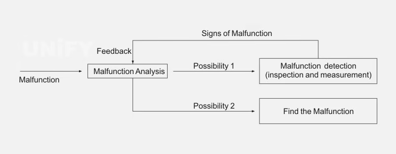
Figure 4-1 Fault diagnosis flow chart
Principles of LED Display Repair
(1) Familiarize yourself with the circuit principle and determine the repair plan
(2) Analyze and think first, then start repairing
(3) Start with the external, then the internal
(4) Start with the simple, then the complex
(5) Start with static, then dynamic
(6) Clean first, then repair
(7) Start with the power circuit, then the functional circuit
(8) Start with the general, then the special
(9) Check peripherals first, then replace
(10) Troubleshoot first, then debug
(11) Start with DC, then AC
(12) Measure without power first, then test with power
(13) Start with the common circuit, then the dedicated circuit
3. General Procedures for LED Display Repair
(1) Observe and investigate the fault phenomenon
(2) Understand the fault
(3) Try to use the faulty LED display
(4) Analyze the cause of the fault
(5) Initially determine the fault range and narrow down the fault location
(6) Summarize the general location or range of the fault
(7) Determine the location of the fault
(8) Troubleshooting
(9) Troubleshooting
(10) Restore and debug
2 LED Display Screen Fault Inspection Methods
1. Intuitive Method
The intuitive method means finding and analyzing faults based on the external symptoms of the LED display without using any instruments. Direct observation includes both powering-off and powering-on inspections. In maintenance, a powering-off inspection should be performed first. Use human senses (eyes, ears, hands, nose) to check for phenomena such as:
Loose plugs or poor contact
Cold solder joints or detached solder
Open circuits or short circuits
Component corrosion, scorching, or discoloration
A blown fuse
The intuitive method is the most basic and simplest method. By observing and checking for various abnormal phenomena like light, sound, and smell that occur during a fault, the maintenance personnel can narrow down the fault to a specific module or even a single printed circuit board. However, it requires the maintenance personnel to have rich practical experience.
Before performing an intuitive inspection, you should ask the on-site personnel about the situation, including the external symptoms of the fault, the approximate location, and the environmental conditions when the fault occurred (e.g., whether there were abnormal gases, open flames, heat sources near the screen, corrosive gases, water leaks, or if someone had previously repaired it).
The implementation of the intuitive method should follow the principle of “simple first, then complex” and “outside first, then inside.” In practice, the first step is to accurately identify the shape, name, representative letter, circuit symbol, and function of all kinds of electronic components inside the LED display. The intuitive method for inspection is mainly divided into the following three steps:
(1) LED display appearance inspection. Check the appearance of the LED display for any signs of collision and whether the external wiring is damaged.
(2) LED display internal inspection. Observe the circuit board and various devices inside the screen.
Check if the fuse is blown.
Check if any components are touching, have broken wires, or if resistors are scorched or discolored.
Check if electrolytic capacitors are leaking, bulging, or deformed.
Check if the copper foil and solder joints on the printed circuit board are in good condition and if there are any signs of previous repairs. When inspecting the inside, you can move some components and parts by hand to check them thoroughly.
(3) Inspection after powering on.
Eyes: Look for sparks or smoke inside the display.
Ears: Listen for any abnormal sounds.
Nose: Smell for any scorched odor.
Hands: Feel if any transistors or integrated circuits are hot to the touch. If there is abnormal heat, you should turn off the power immediately.
The intuitive method is very simple and does not require other instruments. It is very effective for general and damage-related faults. Its effectiveness is strongly correlated with the technician’s experience, theoretical knowledge, and professional skills. The intuitive inspection method requires continuous accumulation of experience through a large number of practical repairs to be used proficiently. This method is often used throughout the entire repair process and is more effective when used in conjunction with other detection methods.
2. Comparison Method
The comparison method is a technique for finding the cause of a fault by comparing the characteristics of a faulty circuit with the correct characteristics. When a certain circuit is suspected, its parameters can be compared with the parameters of a normal circuit in the same working state (or with theoretically analyzed current, voltage, and waveform values). This method is most suitable when a circuit diagram is not available. During maintenance, you can compare the measured data with the drawings, documentation, and normal parameters recorded during normal operation to determine the fault. For LED displays with no documentation or recorded normal parameters, you can compare them with a good LED display of the same model to find abnormal situations in the circuit, and then analyze the cause and determine the fault point. The comparison can be an analogy of identical circuits within the same screen or a comparison between a faulty circuit board and a known good one, which helps the technician quickly narrow down the fault inspection range.
3. Replacement Method
The replacement method is a diagnostic technique for judging a fault by replacing a suspected and difficult-to-measure electrical component or circuit board on the faulty LED display with a new one of the same specification and good performance. Sometimes, when a fault is more hidden, the cause is not easy to determine, or the inspection time is too long, you can use a good component of the same model to replace it to narrow the fault range and further find the fault. This also confirms whether the fault was caused by that component. When using the replacement method, you should note that after removing the suspected faulty component or circuit board, you must carefully check its peripheral circuits. You should only replace it with a new component or circuit board if you are certain that the fault was caused by the component or board itself, to avoid damaging the new part.
Additionally, when the fault status of certain components (such as a capacitor with reduced capacity or leakage) cannot be determined with a multimeter, you should replace it with a new component or connect a good component in parallel to see if the fault changes. If a capacitor is suspected of having poor insulation or a short circuit, one end needs to be unsoldered for testing. When replacing a component, the new component should be of the same model and specification as the damaged one whenever possible.
When the fault analysis concludes that the problem is on a specific printed circuit board, it can be very difficult to pinpoint the fault to a specific area or component due to increasing circuit integration. To shorten the inspection time, you can first replace the board with a spare if available, and then inspect and repair the faulty board later. When replacing a spare board, you should pay attention to the following issues:
(1) Replacement of any spare part must be done with the power off. (2) Many printed circuit boards have switches or shorting jumpers to match specific needs. Therefore, when replacing a spare board, you must record the switch positions and settings on the original board and set the new board in the same way, otherwise, it will cause an alarm and fail to work properly. (3) The replacement of some printed circuit boards also requires specific operations afterward to complete the establishment of software and parameters. This requires carefully reading the user manual for the corresponding circuit board. (4) Some printed circuit boards should not be pulled out easily, such as boards containing working memory or backup batteries, as they may lose useful parameters or programs. If they must be replaced, you must follow the relevant instructions.
Using a spare board of the same model to confirm a fault is a very effective way to narrow the inspection range. If the control board of an LED display has a problem, there is often no other way but to replace it, because most users will not have the schematic diagram and layout, making it difficult to perform chip-level repairs.
Given the above conditions, before pulling out the old circuit board and replacing it with a new one, you must carefully read the relevant information, understand the requirements and operation steps, and then proceed, to avoid causing a bigger fault. The replacement method is highly accurate in determining the cause of a fault, but it can be cumbersome and sometimes difficult to operate, and may cause some damage to the circuit board. Therefore, the use of the replacement method should be based on the specific situation of the LED display fault, as well as the technician’s existing spare parts and the difficulty of replacement. In the process of replacing electrical components or circuit boards, the connections must be correct and reliable, and you must not damage other surrounding components, in order to correctly judge the fault, improve the repair speed, and avoid causing man-made faults.
In the repair of LED display faults, if a two-pin component is suspected of being an open circuit, you may not need to remove it. Instead, you can solder a component of the same specification on top of its pins. If the fault disappears after soldering, it proves that the suspected component was an open circuit, and you can then cut off the faulty component. When a capacitor’s capacity is suspected to have decreased, you can also judge it by connecting a new one in parallel. The precautions for using the replacement method are as follows:
(1) Do not use the replacement method extensively, as this will not only fail to repair the faulty LED display but may even expand the scope of the fault. (2) The replacement method is generally only used after other detection methods have been applied and a component is highly suspected. (3) When the component to be replaced is at the bottom of the board, use the replacement method with caution. If you must use it, you should fully disassemble the screen to expose the component and have enough operating space for replacement.
4. Plug-and-Pull Method
The method of finding a fault by “inserting” or “pulling out” functional circuit board plugins, although simple, is a common and effective method that can quickly find the cause of a fault. The specific steps are as follows:
(1) First, pull out all plug-in boards that are connected to the faulty LED display and all auxiliary circuits. Then, turn on the power switch. If the fault still occurs, you should carefully check the main circuit and the motherboard for faults. (2) If the fault disappears, carefully check each plug-in board for any collisions or short circuits (e.g., touching wires, shorting, touching pins). If there are any, eliminate them. If not, plug in the first board and check again. Continue this process with the remaining boards until you find the faulty plug-in board. Then, based on the fault phenomenon and nature, you can determine which integrated circuit or electronic component is damaged. This way, you can quickly find which plug-in board has a fault.
5. System Self-Diagnosis Method
This method fully utilizes the self-diagnosis function of the LED display. Based on the displayed fault information and the indicators of devices such as light-emitting diodes, you can determine the general cause of the fault. By further utilizing the system’s self-diagnosis function, you can also display the status of various interface signals of the LED display, and find the general location of the fault. It is one of the most common and effective methods in the fault diagnosis process.
All LED displays give fault indications in different ways, which is very important information for technicians. Usually, the LED display will give corresponding fault information for faults related to voltage, current, temperature, and communication.
6. Parameter Inspection Method
LED display parameters are a prerequisite for its normal operation and directly affect its performance. Parameters are usually stored in the system memory. Once the battery is low or the system is interfered with by external factors, some parameters may be lost or changed, preventing the LED display from working properly. By checking and adjusting the parameters, you can sometimes quickly eliminate a fault. This is especially true for LED displays that have been unused for a long time, where parameter loss often occurs. Therefore, checking and restoring the LED display parameters is one of the effective methods in maintenance. In addition, after an LED display has been running for a long time, the performance of electrical components may change, and the relevant parameters may need to be re-adjusted.
LED displays are set with many modifiable parameters to suit different applications and operating conditions. These parameters not only match the system to the specific LED display but are also necessary to optimize all its functions. Therefore, any change (especially in analog parameters) or loss of parameters is not allowed. However, the change in the electrical performance of components caused by the long-term operation of the LED display will break the initial matching and optimal state, which requires re-adjusting one or more related parameters. This method requires a high level of expertise from the technician, who must not only be very familiar with the main parameters of the specific system but also have rich experience in debugging LED display systems.
7. Open-Circuit Method
The open-circuit method is a way to find a fault by manually unsoldering a certain branch or a lead of a component in the circuit. It is sometimes called the “cut-off method.” It is an effective method to quickly narrow down the fault range. You can cut off a certain circuit or unsolder the wiring of a component to compress the fault range. For example, if the current in an LED display’s power supply circuit is too large, you can gradually disconnect suspicious parts of the circuit. The level where the current returns to normal is where the fault lies. This method is often used to repair faults with excessive current and blown fuses.
If you encounter a short circuit or ground fault that is difficult to check, you can replace the old fuse with a new one and gradually or selectively connect each branch to the power supply one by one to test again. When you connect a certain circuit and the new fuse blows again, the fault is in the circuit you just connected and its electrical components.
For multi-branch interconnected circuits, you should selectively disconnect the circuit at a certain point, then power it on and test. If the fuse no longer blows, the fault is in the circuit you just disconnected. Then, you can divide this branch into several segments and connect them to the circuit one by one. When you connect a certain segment and the fuse blows again, the fault is in this segment and a certain component. This method is simple, but it can easily burn out electrical components that were not severely damaged.
8. Short-Circuit Method
LED display faults can be roughly summarized as short circuits, overloads, open circuits, grounds, wiring errors, faults in the peripheral circuits of the LED display, etc. Among these faults, open circuits are more common. They include broken wires, poor connections, loose connections, poor contact, cold solder joints, false solder joints, blown fuses, etc. For this type of fault, in addition to using the resistance method and voltage method, a simpler and more reliable method is the short-circuit method. The short-circuit method uses a well-insulated wire to short-circuit the suspected open-circuit part. If the circuit works normally after a short-circuit at a certain point, it indicates that there is an open circuit at that point. When applying the short-circuit method, you can directly short-circuit to ground for low potential points. For high potential points, you should use an AC short-circuit, which is to short-circuit to ground with an electrolytic capacitor of 20 μF or more, to ensure that the DC high potential does not change. The short-circuit method cannot be used on power supply circuits at will. The short-circuit method is essentially a special kind of circuit division method.
9. Instrument Measurement and Comparison Method
This method uses conventional electrical instruments to measure various AC and DC power supply voltages and pulse signals to find the component causing the fault. For example, you can use a multimeter to check the working condition of each power supply and measure the related signal status measurement points on some circuit boards. You can use an oscilloscope to observe the amplitude and phase of related pulse signals. This method is relatively simple and direct. Based on the fault phenomenon, you can generally determine the location of the fault, and with the help of some measuring tools, you can further determine the cause of the fault and help analyze and judge it.
When LED display printed circuit boards are manufactured, they are equipped with test terminals for convenient adjustment and maintenance. Technicians can use these test terminals to measure and compare the differences in voltage or waveform between a normal printed circuit board and a faulty one, and then analyze and judge the cause and location of the fault. When repairing an LED display, the measurement and comparison method can sometimes also correct “faults” caused by improper adjustment and settings on a circuit board that has been repaired.
The prerequisite for using the measurement and comparison method is that the technician should know the normal voltage values, correct waveforms, and other data for the key parts and fault-prone parts of a normal printed circuit board in order to perform a comparison and analysis. This data should be recorded at all times and accumulated as documentation. Common measurement and comparison methods are as follows:
(1) Voltage Measurement and Comparison Method. This is a detection method for judging faults by measuring the working voltage of electronic circuits or components and comparing them with normal values. The voltages that are frequently tested are the power supply voltage of each stage, the voltage of each pole of a transistor, and the voltage of each pin of an integrated circuit. Generally speaking, the measured voltage results are an important basis for judging whether the LED display’s working status is normal. The part where the voltage deviates significantly from the normal value is often the location of the fault. The voltage measurement and comparison method can be divided into DC voltage detection and AC voltage detection.
AC voltage detection. In LED display circuits, since there are fewer AC circuits, the circuits are relatively simple, and the measurement is easier. You can generally use the AC voltage range of a multimeter to measure from the power input of the LED display. If it is normal, then check whether the AC terminal voltage of the switching power supply is normal to determine the fault location of the front-end power supply.
DC voltage detection. For DC voltage detection, first check the output of the switching power supply circuit. Based on the high or low voltage measured at the input and output terminals, you can further determine which part of the circuit or which component has a fault. When measuring the voltage of a unit circuit, you should first measure the power supply circuit of that unit. Usually, a voltage that is too high or too low indicates that there is a fault in the circuit. When using the DC voltage method to detect the working voltage of each pin of an integrated circuit, you should compare the measured value with the data provided in the repair documentation to determine whether the IC is good or bad.
You can usually measure AC and DC voltage directly with a multimeter, but you must pay attention to the selection of the range and gear of the multimeter. Voltage measurement is a parallel measurement. During the measurement process, you must be focused to avoid short-circuiting two solder joints with the probes.
(2) Current Measurement and Comparison Method. This is a repair method for judging an LED display fault by detecting the working current of transistors, integrated circuits, the current of each local circuit, and the load current of the power supply. When using the current method to detect electronic circuits, you can quickly find the cause of a transistor or electrical component overheating. It is also a common method for detecting the working state of an integrated circuit. When using the current method, you often need to disconnect the circuit and connect the multimeter in series with the circuit. Since this step is more difficult to implement, there are two types of current detection: direct measurement and indirect measurement.
Indirect current measurement is actually using the measured voltage to calculate the current or using a special method to estimate the current. For example, if you want to measure the current of a certain pole of a transistor, you can calculate the current value by measuring the voltage drop across the series resistor on its collector or emitter. The advantage of this method is that you don’t need to create a measurement port on the printed circuit board. In addition, some electrical appliances have temperature-fused resistors on key circuits. By measuring the voltage drop across this type of resistor and applying Ohm’s law, you can estimate the load current in each circuit. If a temperature-fused resistor in a certain circuit is burned out, you can directly measure the current with the multimeter’s current range to determine the cause of the fault.
When an LED display’s fuse blows or a local circuit has a short circuit, the current method is very effective. Current is a series measurement, while voltage is a parallel measurement. In practice, the voltage method is often used first, and the current method is only used when necessary.
(3) Resistance Measurement and Comparison Method. This is a method for judging faults by measuring the resistance of a component to ground or its own resistance. It is effective for repairing open-circuit and short-circuit faults and for determining faulty components. By measuring the resistance of resistors, capacitors, inductors, coils, transistors, and integrated circuits, you can determine the specific location of the fault.
The resistance measurement and comparison method is one of the most basic methods for repairing faults. Generally, there are two methods: “in-circuit” resistance measurement and “out-of-circuit” measurement. When measuring resistance “in-circuit,” since the component being measured is connected to the entire circuit, the resistance value measured by the multimeter is affected by other parallel branches, which should be considered when analyzing the test results to avoid misjudgment. The measured resistance value will be equal to or less than the actual marked resistance value of the component. If it is greater, the component being measured is faulty.
When measuring resistance “out-of-circuit,” you need to unsolder one end of the component or the entire component from the printed circuit board, and then use a multimeter to measure the resistance of the component. This method is more cumbersome to operate, but the measurement results are accurate and reliable.
When using the resistance measurement and comparison method, you should generally test the in-circuit resistance first. After measuring the resistance of each component, you should swap the red and black probes of the multimeter and test the resistance again. This can eliminate the interference of the circuit on the measurement results. You should analyze the results of the two measured resistance values. For a highly suspected component, you can unsolder one end to further test it. In-circuit testing must be done with the power off, otherwise, the measured results will be inaccurate and the multimeter may be damaged. When detecting some integrated circuits that are powered by low voltage (such as 5V, 3V), do not use the R×10k range of the multimeter to avoid damaging the integrated circuit.
There are a few points to pay attention to when applying the resistance measurement and comparison method in practice:
Pay attention to the common “ground” in the detection. To ensure the normal progress of maintenance, the detection instrument and the LED display being repaired must have a common “ground” point.
Pay attention to the high-voltage “series point series line” phenomenon. A faulty LED display often has insulation breakdown, which causes high voltage to string through points and lines, endangering personal safety, damaging measuring instruments, and affecting measurement data. This should be paid attention to.
Follow the repair procedure of “power off before measuring, connect after disconnecting.” Especially for high-voltage measurement, you should first cut off the power supply. To prevent electric shock from the charge stored in large-capacity capacitors, you should discharge them fully before connecting the test leads to ensure personal safety.
The test leads must have good insulation.
Before testing, you must have a full understanding of the detection instrument and the principle of the circuit being tested.
10. Waveform Method
The waveform method is a repair method that uses an oscilloscope to track and observe the changes in the signal at each test point of a signal circuit. It judges a fault based on the presence, size, and distortion of the waveform. The characteristics of the waveform method are that it is intuitive, fast, and effective. An oscilloscope can directly display the signal waveform and measure the instantaneous value of the signal. Some advanced oscilloscopes also have the function of measuring electronic components, which provides a very convenient means of detection. Do not use an oscilloscope to measure high-voltage or high-amplitude pulse parts. When an oscilloscope is connected to a circuit, you should pay attention to the bypass effect of its input impedance. High-impedance, low-input capacitance probes are usually used, and the shell and ground terminal of the oscilloscope should be well-grounded during measurement.
Usually, the schematics of LED displays are marked with clear waveform diagrams at the test locations. These waveform diagrams are an important basis for the waveform method. The waveform method uses measuring instruments to observe the waveform, amplitude, frequency, and position characteristics in the circuit, and can also observe various phenomena such as parasitic oscillations and parasitic modulations. The waveform method is a very effective method for finding, discovering, and eliminating faults, especially for difficult faults. It is very convenient to use this method. The waveform method is also called the dynamic observation method. This method is a detection method when the circuit is in a working state, so you must pay attention to safety during operation.
When using the waveform method for maintenance, there are two types of test instruments commonly used. One is an oscilloscope, which can observe the pulse width, amplitude, period of pulses, the ripple voltage of a stable power supply, and the output waveform of an audio amplifier. The second is a frequency characteristic tester, also known as a sweep frequency generator, which can be used to detect the frequency characteristics, bandwidth, circuit gain, and absorption characteristics of a filter network of various circuits.
11. State Analysis Method
When an LED display fails, the method of analyzing the fault based on the state of the LED display is called the state analysis method. The operation of an LED display can always be decomposed into several continuous stages, which can also be called states. The fault of an LED display always occurs in a certain state, and in this state, what state are the various unit circuits and electrical components in? This is an important basis for analyzing the fault. The more detailed the state division, the more favorable it is for analyzing and judging the fault. When troubleshooting, you must clearly distinguish between various working states, and analyze the working state of each unit circuit and electrical component to find the cause of the fault.
12. Circuit Division Method
The circuit division method is a detection method that separates the circuit involved in a fault from the total circuit. Through detection, you confirm one part and deny another part, narrowing down the fault range step by step until the fault location is isolated.
A complex circuit is always composed of several circuits, and each circuit has a specific function. A fault means the loss of a certain function in that unit circuit, so a fault always occurs in one or more unit circuits. Dividing the circuit actually simplifies the circuit and narrows the fault search range, making it easier to find the fault.
The division method is more convenient to apply to circuits composed of multiple modules, circuit boards, and plug-in connectors. For example, if the fuse in the power supply circuit of an LED display is blown, it indicates that the load current is too large, and the power supply output voltage drops. To determine the cause of the fault, you can connect an ammeter in series at the fuse, and then use the division method to separate the suspected part of the circuit from the total circuit. At this time, you observe the change in the total current. If the current drops to a normal value after a certain part of the circuit is separated, it indicates that the fault is in the separated circuit. There are different division methods, such as the bisection method, characteristic point division method, empirical division method, and point-by-point division method.
The division method is based on a person’s experience to estimate which unit circuit a fault has occurred in, and the input and output terminals of that unit circuit are used as division points. Point-by-point division means to divide the circuit level by level according to the signal transmission sequence, from front to back or from back to front. When using the division method to detect a circuit, you must be careful and pay attention to circuits that cannot be disconnected at will, otherwise, you may not eliminate the fault and may even cause a new one. Strictly speaking, the division method is not an independent detection method, but must be used in conjunction with other detection methods to improve maintenance efficiency.
13. Temperature Increase Method
The temperature increase method is a method to help find faults by artificially increasing the ambient temperature or the temperature of a local component (a hairdryer can be used to increase the ambient temperature of a local component, but be careful not to raise the temperature too high and burn out a component that is working normally). You can heat the suspicious component to accelerate the occurrence of faults in components with poor high-temperature parameters. Sometimes an LED display will fail after working for a long time or when the ambient temperature rises, but it is normal when you turn it off and check it. Then it fails again after working for a period of time. In this case, you can use the “temperature increase method” to check it.
Some LED displays are often normal when they are first turned on, but they fail after a short time, ranging from a few minutes to an hour or two. This is often caused by the poor thermal stability of individual components inside the LED display. Because this type of fault is not fixed, in the repair process, you usually need to make a rough judgment on the fault location based on your experience and the characteristics of the fault phenomenon. You can use a soldering iron or a light bulb to heat the components in the suspicious area. For example, you can use a 20W soldering iron and hold the tip about 1cm away from the suspicious component to heat it locally. If the fault phenomenon reappears immediately when a certain component is heated, you can immediately determine that the fault was caused by the poor thermal stability of that component. The order of heating is transistors, integrated circuits, then capacitors and resistors.
Heating usually has two meanings. One is to accelerate the damage of the component so that the fault appears as soon as possible. The second is to use heating to directly eliminate the fault caused by the circuit board being damp. The opposite method of heating is the cooling method, which is usually used in combination with the heating method. The simplest method is to use cotton dipped in alcohol and apply it to a suspicious component when the LED display fails to cool it down. If the fault disappears when a certain component is cooled, then this component is the faulty one. The cooling method is especially suitable for LED displays that are normal when they are first turned on but fail after a period of use.
14. Tapping Method
The tapping method uses the handle of a small screwdriver or a wooden hammer to gently tap a certain place on the circuit board and observe the situation to determine the fault location (note: high-voltage parts are generally not easy to tap). This method is especially suitable for checking for cold solder joints and poor connections. An LED display is composed of various circuit boards and modules with connectors. Each circuit board has many solder joints, and any cold solder joint or poor connection can cause a fault. After opening the LED display, use an insulated rubber rod to tap the suspicious parts. If the fault of the LED display disappears or reappears, the problem is very likely there.
15. Logical Reasoning and Analysis Method
The logical reasoning and analysis method is a method of analyzing and reasoning from the outside to the inside, tracing the origin, and analyzing and reasoning layer by layer based on the fault phenomenon of the LED display. The various components and functions of the LED display have internal connections. For example, signal transmission, current flow, and voltage distribution all have their own specific laws. Therefore, the failure of a certain part, component, or element will inevitably affect other parts, showing a unique fault phenomenon. When analyzing a fault, you often need to connect this fault to the impact on other parts or find the root cause of the fault from a certain fault phenomenon. This process is a process of logical reasoning. The logical reasoning and analysis method is divided into forward reasoning and reverse reasoning. The forward reasoning method generally analyzes and finds faults from the peripheral circuits, power supply, control circuit, power circuit, and signal circuit based on the fault phenomenon. The reverse reasoning method uses the opposite order to analyze and find faults.
Using the logical reasoning and analysis method to make a specific analysis of the fault phenomenon, and to delineate the suspicious range, can improve the targeting of maintenance and achieve the effect of judging faults quickly and accurately. When analyzing the circuit, you should start with the main circuit, understand the relationship between each unit circuit, and combine the fault phenomenon with the working principle of the circuit to perform a careful analysis and elimination. This can quickly determine the possible range of the fault. When the suspicious range of the fault is large, you don’t have to check level by level in a stepwise manner. At this time, you can check the middle link of the fault range to determine which part the fault occurred in, thereby narrowing the fault range and improving the repair speed.
16. Principle Analysis Method
The principle analysis method is the most fundamental method for troubleshooting. When other inspection methods are difficult to be effective, you can start from the basic principle of the circuit, and check it step by step to finally find the cause of the fault. Using this method requires a clear understanding of the principle of the circuit and mastery of the logic level and characteristic parameters (such as voltage value and waveform) of each point at each moment. Then, you can use a multimeter and an oscilloscope to measure, compare with the normal situation, analyze and judge the cause of the fault, narrow the fault range, and finally find the fault. Using this method requires the technician to have a high level of expertise and a clear and in-depth understanding of the entire system or each part of the circuit.
In general, to inspect a faulty LED display, you should go from the outside to the inside, from the surface to the inside, from static to dynamic, and from the main circuit to the control circuit, and then to the signal circuit. Although there are many methods for inspecting LED display faults, which inspection method is more effective in actual repair depends on the specific situation of the fault.
When repairing an LED display, you usually use the intuitive method first. Some typical faults can often be solved in one go with the intuitive method. For more hidden faults, you can use the oscilloscope method. For faults that are not easy to test, you often use the replacement method, short-circuit method, and division method. The application of these methods can often compress the fault to a smaller range, thereby improving the efficiency of the maintenance work. It must be emphasized that each detection method can be used to detect and judge a variety of faults, and the same fault can also be repaired with a variety of detection methods. During maintenance, you should flexibly apply various detection methods to ensure that the detection work achieves twice the result with half the effort.
After finding the fault point of the LED display, you should start the repair, trial run, and recording, and then hand it over for use. However, you must pay attention to the following matters:
- (1) When finding the fault point and repairing the fault, you should pay attention not to treat the found fault point as the end point of finding the fault. You must further analyze and find the root cause of the fault.
- (2) After finding the fault point, you must adopt the correct repair method for different fault situations and locations.
- (3) In the repair work of the fault point, you should generally try to restore it to the original state.
- (4) After the fault is repaired, if a trial run with power on is required, you should follow the operating steps to avoid new faults.
- (5) After each troubleshooting, you should summarize the experience in a timely manner and make a maintenance record. The content of the record includes: the LED display model, number, date of the fault, fault phenomenon, location, damaged electrical components, cause of the fault, repair measures, and the operating status after the repair. The purpose of the record is to summarize maintenance experience, to be used as a file for future maintenance reference, and to improve maintenance skills and practical operation skills through the accumulation of experience from previous fault repairs.
In short, the repair process of an LED display is a comprehensive analysis process. It is built on a deep understanding of the circuit structure, correct and accurate logical thinking and judgment, and proficient operation skills. Judging faults requires a good theoretical knowledge as a foundation. Only by carefully mastering the general laws of maintenance and continuously summarizing and accumulating experience can you accurately and timely find and solve problems. In addition, when looking for faults, try to broaden your thinking, think of all the factors that can cause the fault, and analyze and eliminate them carefully.
In actual maintenance, there are many ways to find the cause of a fault. The use of these methods can be flexibly grasped according to the equipment conditions and fault situation. For simple faults, one method can find the fault point. However, for more complex faults, a variety of methods need to be used to complement and cooperate with each other to quickly and accurately find the fault point.
Recommend Products

Outdoor LED Screen Price Guide 2025: What Buyers Really Need to Know
2025 outdoor LED screen price guide: UnifyLED rental and permanent screens with high brightness, durability, and front-access design.
Outdoor LED Module Buying Guide: Avoid Common Mistakes
Outdoor LED module buying guide: specs, prices, and mistakes to avoid. Explore our tips today.
UK P2.5 Indoor LED Display Installation: RCCG Church Case Study by Unify
UK P2.5 Indoor LED Display Installation: RCCG Church Case Study by Unify Elevating Worship with P2.5 Indoor LED Display: Unify’s