LED Display Installation and Auxiliary Design
- Home
- »
- Installation & Maintenance
- »
- LED display installation
Table of Contents
LED Display Cabinet and Installation MethodsLED
1. LED Display Cabinet
LED Display Outer Frame Structure and External Decoration
The outer frame structure of an LED display is designed based on installation requirements, display area size, and surrounding environmental colors. The design aims to ensure sufficient installation strength while minimizing the installation weight. For indoor LED displays, the outer frame design typically includes three types:
- Brown Aluminum Alloy Frame: Simple structure, with a color similar to the display background.
- Aluminum Alloy Frame Wrapped with Stainless Steel: Uses brushed stainless steel for an aesthetically pleasing and elegant appearance.
- Integrated Sheet Metal Structure (Sony Gray): Visually appealing and compact with no gaps. However, this structure has specific requirements for the LED display size.
For outdoor LED displays, steel structures are typically used to ensure sufficient installation strength. External decoration is chosen based on site conditions and user requirements, with aluminum composite panels being a common choice due to the following advantages:
- Available in various colors and types, allowing customization based on requirements.
- High surface quality with low roughness.
- Supports seamless splicing with evenly spaced surface lines, meeting aesthetic requirements.
LED Display Cabinet Classification
LED display cabinets are classified by purpose into two types:
- Waterproof Cabinets: Used for outdoor LED displays, featuring waterproof, dustproof, and wind-resistant functions, meeting international IP standards (commonly IP65 or IP68).
- Simple Cabinets: Used for indoor or semi-outdoor LED displays, without waterproof capabilities.
By material, cabinets are divided into:
- Iron Cabinets: Made of cold-rolled steel (thickness: 1.0mm, 1.2mm, or 1.5mm).
- Aluminum Cabinets: Made of 5052 aluminum alloy (thickness: 2mm).
By protection method, cabinets are classified as:
- Indoor Sealed Cabinets.
- Outdoor Waterproof Cabinets.
By installation method, cabinets are categorized as:
- Rack-Mounted Cabinets.
- Hanging Cabinets.
- Embedded Cabinets.
LED Display Cabinet by Maintenance Method
Cabinets are divided into:
- Rear Maintenance Cabinets.
- Front Maintenance Cabinets: Allow maintenance personnel to directly access and replace components from the front of outdoor LED displays.
By structure, cabinets are classified as:
- Standard Cabinets.
- Custom-Shaped Cabinets.
LED Display Assembly
For smaller LED displays, the screen is assembled into a complete unit at the factory. For larger displays, the screen is shipped in unit board form and assembled on-site by engineers. During assembly:
- Unit boards and power supplies are fixed to the back frame.
- For cabinet-based LED displays, prefabricated LED display module units are installed into individual cabinets, which are then spliced onto the steel structure to form the complete LED display.
- Connectors between cabinets, such as positioning pins and locking mechanisms, ensure secure and precise installation, maintaining vertical and horizontal spacing of LED beads within the required tolerance range to guarantee the overall display effect.
2. LED Display Installation Methods and Precautions
Simple Frame Structure Display Installation Methods
An LED display has a six-sided structure, with only the front serving as the display surface (non-load-bearing). The other five sides can be used for load-bearing connections.
- Back Installation: Common methods include wall-mounted installation or fixing the entire unit to a wall.
- Top Installation: Typically involves suspension.
- Side Installation: Often used for screens mounted between two pillars.
- Bottom Installation: Includes standalone pillar support or base installation.
- Hybrid Installation: Involves multiple sides for load-bearing, commonly used in embedded installations.
(1) Suspension Installation
Suspension installation involves setting load-bearing points on a wall and hanging the LED display, using the wall as a fixed support. This method is suitable for indoor or semi-outdoor LED displays under 10 square meters, requiring a solid wall or a concrete beam at the suspension point. Hollow bricks or simple partition walls are unsuitable for this method.
Steps for Suspension Installation:
- Secure connectors (e.g., angle iron) to the wall using expansion bolts, ensuring connectors at the same height are aligned horizontally.
- Hang the frame (equipped with a power supply) onto the connectors, measure diagonals to ensure the frame is not deformed, and secure it with self-tapping screws.
- Use suction cup magnets to install unit boards, adjusting suction cup height to ensure the flatness of the entire LED display.
Wall-Mounted Installation
Wall-mounted installation is suitable for LED displays with a total weight below 50kg. For smaller display areas, maintenance access is typically not reserved, requiring the entire screen to be removed for maintenance or designed as a foldable integrated frame. For slightly larger screens, front maintenance design is generally used (e.g., column-style assembly).
Schematics:
- Refer to Figure 2-1 for general wall-mounted installation.
- Refer to Figure 2-2 for wall-mounted installation schematic.
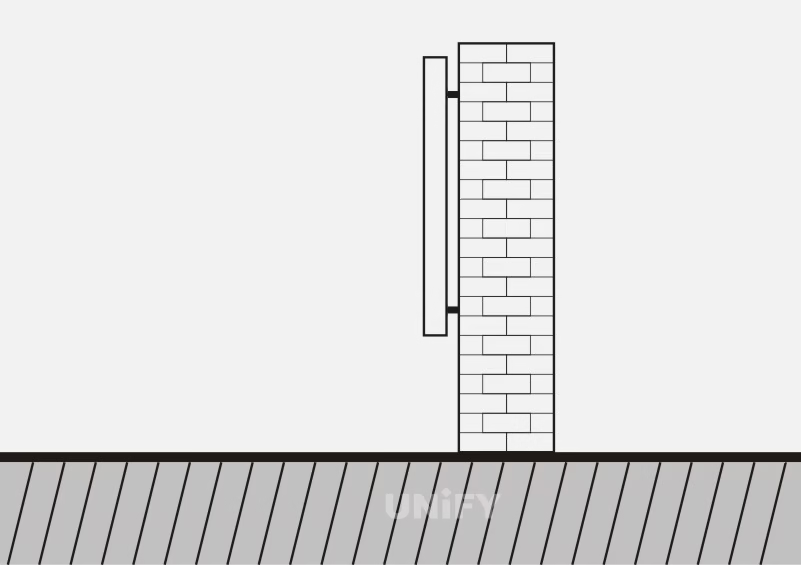
Figure 2-1 Standard Mounting
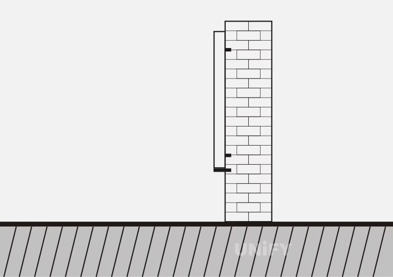
Figure 2-2 Wall Mounting
(2) Rack Installation. Rack installation is suitable for LED displays over 10m² and is convenient for maintenance, requiring the wall to be a solid wall, a marble wall with a steel frame, or a hanging point with a concrete beam. Other specific requirements are the same as wall-hanging installation. The rack installation diagram is shown in Please insert Figure 2-3 Rack Installation Diagram. Due to a certain distance between the frame and the wall, influenced by gravity, and considering that the frame may tilt toward the wall, a support frame should be installed at the corresponding position below the frame.
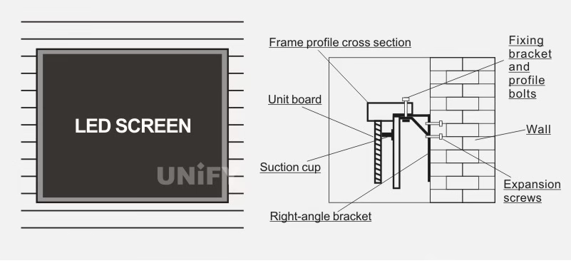
Figure 2-3 Schematic diagram of rack installation
(3) Hanging Installation. Hanging installation involves suspending the LED display screen body on a pre-fabricated steel structure, suitable for LED displays serving as signage in large venues like stations and airports. It is also used on stages or outdoors without wall support, with temporary LED displays benefiting significantly from this method.
Hanging installation is suitable for displays under 10m² with a weight not exceeding 50kg. This installation method requires a suitable location, such as an overhead beam or lintel. The screen body generally needs a rear cover, and the display box adopts front maintenance design, allowing the screen to be lifted from the bottom for maintenance.
If the LED display is under a beam or lintel, expansion bolts can be used to fix pre-prepared threaded hanging rods, with the rod length determined by site conditions and fitted with flanges and stainless steel pipes matching the screen body color. If the LED display is under a steel beam on a ceiling, steel wire ropes are used for hanging. The perforated frame is suspended above, secured with screws or wire rope clips, and diagonals are measured to ensure the frame is not deformed. Then, unit panels with pre-prepared suction cup magnets are installed and connected. For indoor load-bearing concrete roofs, standard hanging fittings can be used, with rod length depending on site conditions.
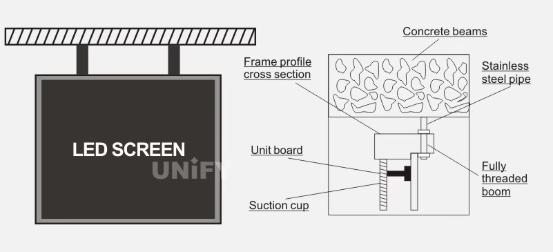
Figure 2-4 Hoisting diagram
(4) Base Installation. Base installation involves mounting the LED display on a platform, requiring the fabrication of a screen body steel structure and a concrete base, with primary consideration given to the geological conditions of the foundation.
Movable Base Installation: Refers to a base frame processed separately and placed on the ground, allowing movement.
Fixed Installation: Refers to a base frame connected to the ground or wall as a fixed structure.
Whether movable or fixed, the base frame must be measured with a level to ensure it is level before installation.
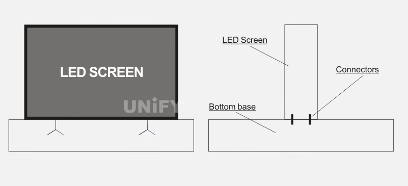
Figure 2-5 Seat installation diagram
Installation Methods for Outdoor Cabinet Structure LED Displays
The outdoor environment not only demands high quality for LED displays but also imposes stricter requirements on their installation. Installation methods vary depending on the specific outdoor location. The main installation methods for outdoor LED displays include:
(1) Ground-Supported Installation: This method is suitable for LED displays without a fixed position, such as those installed on a fixed concrete platform.
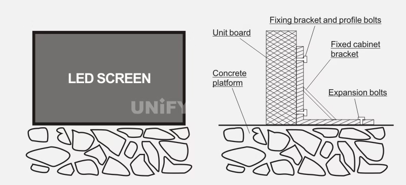
Figure 2-6 Schematic diagram of floor-supported installation
(2) Pillar Installation. When there are no walls or available support points, pillar installation can be used, but it has higher requirements for the steel structure. Outdoor LED displays often adopt pillar installation, such as those along highways. Pillar installation is divided into single-pillar and dual-pillar types, as shown in Figure 2-7. Single-pillar installation is suitable for smaller display areas, while dual-pillar installation is suitable for larger display areas. Enclosed maintenance channels are suitable for simple cabinets, while open maintenance channels are suitable for standard cabinets.
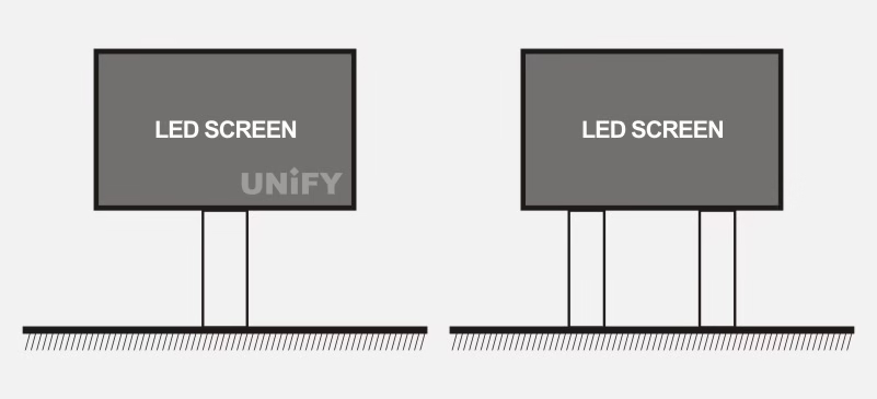
Figure 2-7 (a) Single-Pillar Installation Method; (b) Double-Pillar Installation Method
(3) Rooftop Style. LED displays installed in city squares often use the rooftop installation method, mounted on the roofs of surrounding buildings. The rooftop installation diagram is shown in Figure 2-8
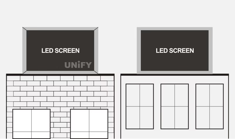
Figure 2-8 Rooftop Installation Method
(4) Embedded Style. The embedded structure involves pre-reserving or opening a cavity in the wall to inset the LED display, requiring the cavity size to match the display’s outer frame dimensions and appropriate decoration. For easy maintenance, the wall cavity must be through, or a front maintenance box LED display must be used. The embedded installation method generally involves adding a steel structure to the wall, using it as support to embed the outdoor LED display, primarily in building facades. The embedded installation diagram is shown in Figure 2-9.
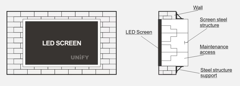
Figure 2-9 Embedded Installation Diagram
The screen body frame structures of the above four installation methods are consistent, differing only in the load-bearing support points. The requirements for the LED display screen body frame are as follows.
(1) The rear of the LED display screen must leave at least 600mm of space as a maintenance channel, with a maintenance channel every 3–4 box heights to facilitate installation and maintenance.
(2) Ladders must be welded between upper and lower maintenance channels.
(3) Each maintenance channel must have lighting.
(4) Ensure that the square steel fixing the boxes and the box contact surfaces remain on the same level.
(5) When assembling box-type LED displays, positioning pins are used between boxes for alignment, and connection pieces and screws are used for tightening to ensure flatness between boxes.
(6) The installed LED display must be level left and right, with no forward or backward tilt. Hanging installations require upper and lower adjustment rods, wall-mounted installations require forward tilt fall-off hooks, and ground installations require positioning support bolts.
LED Display Civil Engineering Foundation
The LED display civil engineering foundation is the base that bears the weight of the outdoor LED display screen body. Its functions are twofold: one is to evenly distribute the screen body’s weight onto the foundation to prevent settlement, and the other is to balance the wind load on the screen body to prevent tipping. The LED display civil engineering foundation mainly consists of the foundation part, bearing platform, reinforced concrete foundation, embedded parts, and backfill soil.
The embedded parts in the LED display civil engineering foundation involve pre-fabricated steel components buried in the concrete during pouring, providing a solid foundation for the installation of future external components. Commonly used embedded parts include pre-cast bolts and pre-cast steel plates.
LED Display Auxiliary Design
1.LED Display Environmental Protection
(1) LED Display Environmental Protection Requirements
LED displays must meet the following environmental protection design requirements:
- Physical Protection: Waterproof, moisture-proof, dust-proof, corrosion-resistant, fire-resistant, and resistant to industrial interference.
- Electrical Protection: Overcurrent, short-circuit, open-circuit, overvoltage, undervoltage, anti-static, anti-electromagnetic interference, vibration-resistant, and lightning-resistant.
- Products must undergo waterproof, moisture-proof, dust-proof, fire-resistant, corrosion-resistant, and mildew-resistant treatments, passing salt spray tests to meet national industrial standards, ensuring long-term normal operation even in heavily polluted environments.
(2) Physical Environment for LED Display Operation
Each LED display has specific environmental technical requirements, which must be fully considered during selection. Due to the compact structure and significant heat dissipation of LED displays, the installation environment must meet high standards for temperature, humidity, and dust content to ensure a suitable operating environment.
Failure to meet these environmental requirements will result in a high failure rate, affecting long-term, reliable, and safe operation, leading to unnecessary economic losses. To ensure reliability and extend service life, the installation site must meet the following conditions:
- Operating Temperature:
- Electronic components inside the LED display are sensitive to operating temperature. Manufacturers typically specify an environmental temperature range of 0–55°C, but for safe and reliable operation, it is advisable to maintain temperatures below 40°C.
- For naturally cooled LED displays without forced cooling, the internal temperature may be 10–15°C higher than the external temperature. Measures must be taken to address heat dissipation based on the installation site and internal heat generation to ensure the internal temperature does not exceed the display’s operating range.
- Ensure sufficient ventilation space around the display and avoid direct sunlight exposure. The display body should include ventilated louvers, and if internal temperatures are too high, fans should be installed for forced ventilation.
- Environmental Humidity:
- High humidity or significant humidity fluctuations can cause condensation inside the LED display, significantly reducing insulation performance and potentially causing short-circuit incidents.
- If necessary, desiccants and heaters should be added to the display body. To ensure insulation performance, the relative humidity of the air should be less than 85% (non-condensing). In high-humidity environments, the display should adopt a sealed structure, and convection heaters should be installed to prevent condensation when the display is off.
- Corrosive Gases:
- Avoid installing LED displays in environments with high concentrations of pollutants (e.g., dust, oil fumes, iron powder) or corrosive gases, as these can corrode component leads, printed circuit boards, and accelerate plastic component aging, reducing insulation performance.
- In such environments, the display body should be designed as a sealed structure with ventilation.
- Explosive and Flammable Gases:
- Avoid installing LED displays in areas with explosive or flammable gases, as relays inside the display may generate sparks, potentially causing fires or explosions.
- In environments with dust or oil mist, these substances can adhere to and accumulate on the display, reducing insulation. For forced air-cooled displays, clogged filters can cause abnormal internal temperature rises, leading to unstable operation. In such cases, the display body should be sealed if temperature conditions allow.
- Vibration and Impact:
- Install LEDjulia displays away from areas with strong or frequent vibrations and impacts. If unavoidable, measures such as anti-vibration rubber pads should be used to secure the display and internal components to prevent loose connections or components.
- Vibration tolerance varies by display type. Excessive vibration can loosen fasteners or cause relay malfunctions, leading to unstable operation. Anti-vibration measures, such as rubber pads, must be implemented in such environments.
- Altitude:
- LED displays are typically specified for altitudes below 1000m. Higher altitudes reduce air pressure, potentially causing insulation breakdown, and decrease cooling efficiency, requiring attention to temperature rise.
- Operating Space:
- When designing the display body, consider usability, operability, and maintenance requirements, including:
- Sufficient space for easy operation and module replacement, considering tool accessibility.
- Ensuring safety during maintenance operations.
- When designing the display body, consider usability, operability, and maintenance requirements, including:
(3) Electrical Environment for LED Display Operation
The electrical environment for LED displays includes frequency variations, voltage fluctuations, voltage imbalance, power impedance, power harmonics, and other abnormal conditions, such as:
- Frequency variation limit: ±2% of nominal frequency (fLn).
- Rated input voltage variation: ±10%.
- Voltage imbalance: Not exceeding 3% of the fundamental rated input voltage (ULn₁).
The installation site must meet the following electrical environment requirements:
- Power Line Interference:
- LED displays have some resistance to power line interference. In environments with high reliability requirements or severe power interference, a 1:1 isolation transformer with a shielding layer can be installed to reduce interference between the equipment and ground.
- Electromagnetic Interference:
- Electromagnetic waves in the operating environment can interfere with the display’s input and output. In strong electromagnetic environments, the display body should use a metal casing to shield external interference. The grounding terminal must be reliably connected, and in severe electromagnetic interference environments, input and output lines should use shielded cables with grounded shielding layers.
- Overvoltage Protection:
- The power input should have overvoltage protection. Prolonged high voltage can damage the power input. In practice, verify the input voltage, phase, and rated voltage of the LED display.
- Provide an independent power supply circuit and avoid sharing a transformer with loads that cause surges.
- Distance from High-Voltage Equipment:
- To avoid electromagnetic interference from other peripheral equipment, maintain at least 200mm distance between the LED display and high-voltage power lines or equipment.
- Strong Interference Sources:
- Keep LED displays away from strong interference sources, such as high-power thyristors, high-frequency equipment, large power equipment, strong electromagnetic fields, strong radiation sources, and areas prone to strong static electricity.
(4) LED Display Fire Prevention Technology
Fire prevention materials for LED displays include four main aspects: internal wiring, power supply, external protective structure materials, and plastic components.
- Wiring:
- In most LED display applications, larger display areas require higher power consumption, demanding greater wiring stability. Use wires meeting national standards to ensure safety and stability, with requirements including:
- Copper wire core as the conductive carrier.
- Wire core cross-sectional area tolerance within standard limits.
- Insulation and flame-retardant properties of the wire core sheath meeting standards.
- Compared to aluminum wire cores, undersized cross-sections, or substandard insulation sheaths, compliant wires offer more stable performance and are less prone to short circuits.
- In most LED display applications, larger display areas require higher power consumption, demanding greater wiring stability. Use wires meeting national standards to ensure safety and stability, with requirements including:
- Power Supply:
- UL-certified power supplies are the best choice for their category, with high conversion efficiency ensuring safe and stable load operation, even in high external temperatures.
- External Protective Materials:
- High fire-rated LED display products typically use fire-resistant aluminum-plastic panels, which offer excellent fire resistance and flame retardancy. Conventional aluminum-plastic panels age quickly under high temperatures, rain, and thermal shock, allowing moisture to penetrate the display body in humid conditions, potentially causing short circuits and fires.
- Plastic Components:
- Plastic components, primarily used for module mask bottom shells, should use flame-retardant PC+fiberglass materials. These materials are flame-resistant, resist deformation and brittleness at high and low temperatures, and, when combined with high-sealant glue, effectively prevent external rainwater from penetrating and causing short-circuit fires.
External configuration and design are also critical for fire prevention, particularly regarding heat dissipation. During operation, LED displays should be equipped with exhaust fans and air conditioners to cool the internal body. It is recommended to install a 1P air conditioner for every 8–10m² to maintain normal internal temperatures. Inadequate air conditioner or fan configuration can lead to uneven heat dissipation, increasing internal temperatures and posing safety risks. Many LED companies only simulate external spray waterproof tests during protection level assessments, leaving the durability and strength of waterproofing unverified. This can result in water seepage after prolonged use, a key reason for fires or short service life in outdoor LED displays. During thunderstorms, lightning arresters within the display body are essential to prevent lightning damage, directing lightning to the ground without affecting the display.
2.LED Display Power Distribution System Design
(1) LED Display Power Distribution System Requirements
The general requirements for LED display power distribution systems are as follows:
- Power Supply Method:
- For displays with a maximum power of less than 10kW, single-phase three-wire AC power (AC220V) is typically used, with grid voltage fluctuations less than 10% and good system grounding.
- For displays exceeding 10kW, three-phase five-wire AC power (AC380V) is required. Wires include phase, neutral, and ground lines, with phase and neutral lines having the same cross-sectional area.
- Maintenance Lighting:
- Maintenance lighting inside the display should use a safe voltage of 36V or below.
- Single-Phase Circuit Current:
- Each single-phase circuit current should not exceed 16A.
- Maintenance Power Socket:
- Maintenance power sockets should have a dedicated circuit.
- Air Conditioner Circuit:
- Air conditioners should have a dedicated circuit.
The power distribution system should use radial wiring, which offers independent circuits, minimizing mutual impact during faults and ensuring high reliability. However, radial wiring requires more circuits, increasing material costs and initial investment. Common power supply systems for LED displays include three-phase five-wire (TN-S system), three-phase four-wire, and single-phase three-wire systems:
- Three-Phase Five-Wire System:
- Provides three-phase (A, B, C) voltages, one neutral line (N), and one protective ground line (PE), with a phase voltage of 380V and phase-neutral voltage of 220V, suitable for displays.
- Three-Phase Four-Wire System:
- Lacks a protective ground line, typically used for equipment without metal casings, such as lighting, and is not suitable for display power supply.
- Single-Phase Three-Wire System:
- A simplified version of the three-phase five-wire system, providing single-phase voltage, used for displays with power consumption not exceeding 6–8kW.
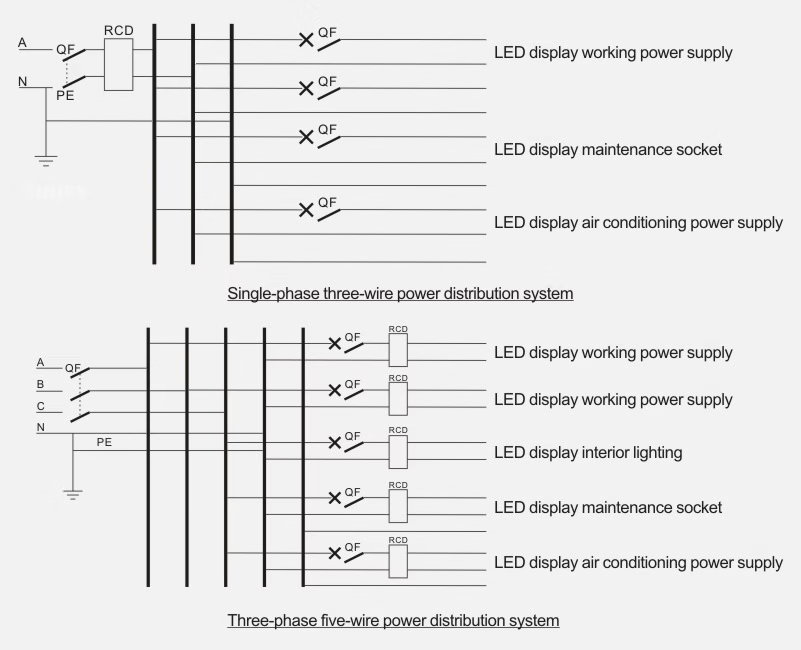
Figure 2-10 LED display power distribution system
- Pure Resistive Load:
- Current calculation: I = Power / 220V.
- Inductive Load:
- Current calculation is more complex, requiring consideration of power consumption and power factor. For simplicity, the calculated current for an inductive load can be doubled.
Total load current is the sum of branch currents. After calculating branch and total currents, select the appropriate branch and main circuit breaker ratings, verifying they meet safety requirements. For safety and reliability, the breaker’s rated operating current should generally be at least twice the maximum required load current. To ensure safety and ease of maintenance, branch power circuits should meet the following requirements:
- Branch Separation:
- The display’s working power, internal lighting, and maintenance socket circuits should be separate to prevent mutual interference during faults and facilitate fault analysis and repair.
- Air Conditioner Branch:
- Air conditioners should have an independent branch circuit, with copper wire cross-sections of 2.5–4mm² (2.5mm² for split air conditioners, 4mm² for cabinet air conditioners).
(3) Leakage Protector Selection
Leakage protector selection should consider the following factors:
- Leakage Action Current:
- Use high-sensitivity, fast-acting leakage protectors (action current ≤10mA). If assistance is available to disconnect power during an electric shock, the action current can exceed the escape current. For primary protection (before branch protection), the action current can exceed the ventricular fibrillation current. In environments where assistance is unavailable, the action current should not exceed the escape current. In cases where electric shock could cause severe secondary accidents, use fast-acting protectors with a 6mA action current.
- Misoperation Prevention:
- The protector should avoid unbalanced leakage currents and not misoperate under electromagnetic interference. Action current selection should consider protector performance, as purely electromagnetic protectors struggle to achieve action currents below 40mA, and overly sensitive protectors should be avoided. For multi-level protection, primary protectors should have lower sensitivity or slight delays.
- Leakage Fire Protection:
- For preventing leakage-induced fires, use medium-sensitivity protectors with action currents of 25–1000mA.
- Pole Selection:
- Single-phase lines use two-pole protectors; three-phase four-wire lines require four-pole protectors.
- Performance Matching:
- The protector’s rated voltage, current, and breaking capacity must match line conditions, and the protector type must suit the power supply line, method, grounding type, and equipment characteristics.
(4) Wire Cross-Section Selection
Commonly used wires include:
- Copper-core PVC-sheathed cables for wiring from distribution cabinets to the display or equipment.
- Copper-core PVC-insulated cables for internal cabinet or display wiring, requiring conduits or cable trays.
- Color coding: A-phase yellow, B-phase green, C-phase red, neutral light blue (or black), PE yellow-green dual-color.
Wire cross-sectional area (mm²) determines the safe current capacity; larger cross-sections allow higher currents. Selection is based on safe current-carrying capacity and considers line distance. For short distances, select wires based on maximum load current plus a margin, meeting heat, voltage loss, and safety requirements. Longer lines require larger cross-sections. Selection principles include:
- Voltage Loss: Must be within allowable limits (<5%) to ensure power quality.
- Heat Conditions: Heat coefficient must be within allowable limits to prevent insulation damage and reduced lifespan.
- Mechanical Strength: Ensure sufficient strength to prevent wire breakage during normal use.
Wire cross-section selection relates to the branch circuit breaker’s current rating, which must be less than the wire’s current-carrying capacity to provide protection. Otherwise, overloads may cause wire overheating or insulation damage without tripping, leading to safety hazards. For a 16A breaker, use copper wires of at least 2.5mm². Never reduce wire cross-sections, substitute copper with aluminum, or arbitrarily increase breaker ratings to avoid tripping.
For low-load equipment, while small cross-sections may meet current requirements, verify they meet minimum mechanical strength requirements. If not, select the minimum cross-section based on mechanical strength.
Copper wire safe current-carrying capacity is determined by maximum core temperature, cooling conditions, and installation conditions, typically 5–8A/mm².
Examples:
- 2.5mm² BVV copper wire: 2.5 × (5–8)A/mm² = 12.5–20A.
- 4mm² BVV copper wire: 4 × (5–8)A/mm² = 20–32A.
To calculate copper wire cross-sectional area, use the safe current-carrying capacity range of 5–8A/mm²: S ≤ I / (5–8) (2-1)
S ≥ 0.125I – 0.2I (mm²) (2-2)
Where S is the wire cross-sectional area (mm²), and I is the load current (A).
Loads are divided into resistive and inductive types:
- Resistive load power: P = U × I (2-3)
- Inductive load power: P = U × I × cosφ (2-4)
For uniform LED display power calculations, assume a power factor (cosφ) of 0.8. For example, for a total load power of 6000W:
I = P / (U × cosφ) = 6000 / (220 × 0.8) = 34A
However, since not all appliances operate simultaneously, apply a simultaneity factor (K, typically 0.7):
I = P × K / (U × cosφ) = 6000 × 0.7 / (220 × 0.8) = 24A
Thus, the total current is 24A, and the main breaker should be rated above 24A.
Power supplies typically use single-phase 220V or three-phase 380V, and wires should use 500V-rated insulation regardless of the supply voltage.
3.LED Display Information Transmission Cables
(1) Information Cable Composition
Information cables consist of:
- Inner Conductor: Affects signal attenuation, with lower resistance being better.
- Insulation: Impacts attenuation, impedance, and return loss.
- Outer Conductor: Serves as a loop conductor and provides shielding.
- Sheath: Protects the cable and enhances durability.
(2) Twisted Pair Structure
Twisted pair (TP) is the most common transmission medium, consisting of two insulated copper wires twisted at a specific density to reduce signal interference. The electromagnetic waves radiated by one wire are canceled by the other. Typically, twisted pair cables contain four pairs: white-orange/orange, white-blue/blue, white-green/green, and white-brown/brown.
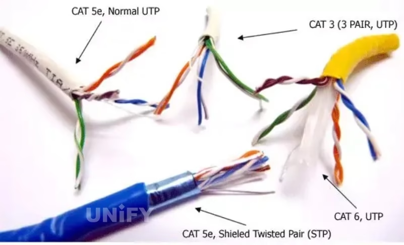
Figure 2-11 Twisted pair cable structure
Applications include telephone voice, computer data, fire and theft prevention, and smart building information transmission. Twisted pairs are classified as Category 5, Category 6, etc., and divided into:
- Unshielded Twisted Pair (UTP): No shielding, cost-effective.
- Shielded Twisted Pair (STP): Wrapped with aluminum foil for enhanced interference resistance.
(3) Twisted Pair Performance Indicators
Key performance indicators affecting transmission include:
- Attenuation: Measures signal loss along the link, increasing with cable length and frequency, expressed in dB as the ratio of transmitted to received signal strength.
- Crosstalk:
- Near-End Crosstalk (NEXT): Measured at the near end, challenging to measure accurately, especially at higher frequencies. NEXT decreases with cable length and signal attenuation.
- Far-End Crosstalk (FEXT): Less impactful due to line losses.
- DC Loop Resistance: Total resistance of a wire pair must be ≤19.2Ω, with pair differences <0.1Ω to avoid poor connections.
- Characteristic Impedance: Includes resistance, inductance, and capacitance impedance at 1–100MHz, typically 100, 120, or 150Ω.
- Attenuation-to-Crosstalk Ratio (ACR): Reflects interference resistance, typically requiring >10dB, also known as signal-to-noise ratio (SNR).
- Cable Characteristics: Signal quality is described by SNR, which measures data signal strength against interference. A low SNR can cause data errors, requiring a minimum acceptable SNR to limit errors.
(4) Twisted Pair Classification
Twisted pair classifications are shown in Figure 2-12.
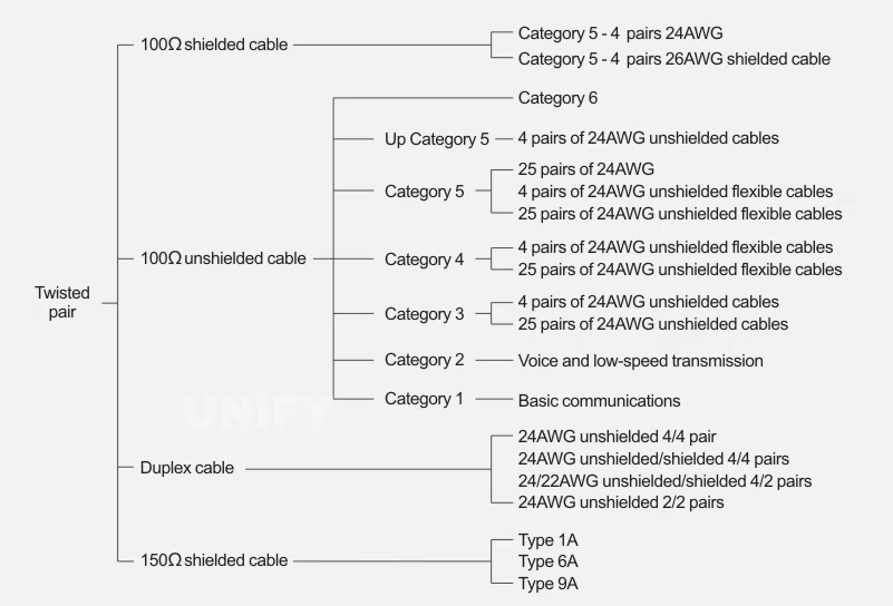
Figure 2-12 Classification of twisted pair cables
- Category 1 (CAT1): Bandwidth 750kHz, used for alarm and voice transmission, not for data.
- Category 2 (CAT2): Bandwidth 1MHz, for voice and data up to 4Mbit/s, used in older token networks.
- Category 3 (CAT3): Bandwidth 16MHz, up to 10Mbit/s, for voice and 10BASE-T Ethernet, largely obsolete.
- Category 4 (CAT4): Bandwidth 20MHz, up to 16Mbit/s, for token-based LANs and 10/100BASE-T, not widely adopted.
- Category 5 (CAT5): Bandwidth 100MHz, up to 100Mbit/s, for 100BASE-T and 1000BASE-T networks, commonly used with RJ connectors.
- Category 5e (CAT5e): Lower attenuation and crosstalk, higher ACR and SNR, used for Gigabit Ethernet.
- Category 6 (CAT6): Bandwidth 1–250MHz, provides double the bandwidth of CAT5e, suitable for >1Gbit/s applications.
- Category 6A (CAT6A): Bandwidth 500MHz, up to 10Gbit/s, standard diameter 6mm.
- Category 7 (CAT7): Bandwidth 600MHz, up to 10Gbit/s, single-wire diameter 8mm, multi-core 6mm, for future 10 Gigabit Ethernet.
Secondary Heading 4: LED Display Lightning Protection Design
(1) Lightning Protection Measures
LED displays are highly susceptible to lightning damage due to their high-density integrated circuits. Lightning can cause mechanical, electrical, and thermal damage, potentially leading to fires. Lightning protection measures must comply with the Code for Design of Lightning Protection of Buildings (GB 50057—1994):
- Direct Lightning Protection:
- For displays not within the protection range of nearby tall buildings, install a lightning rod on or near the display’s steel structure.
- Induced Lightning Protection:
- Install Level 1 and 2 power surge protectors in the display’s power system and Level 3 in the equipment room. Phase wire cross-section ≥10mm², ground wire ≥16mm².
- Install signal surge protectors on signal lines (e.g., network surge protectors for Ethernet, DB9 protectors for serial interfaces).
- Line Protection:
- Use shielded cables for power and signal lines, laid underground.
- Grounding System:
- Front-end grounding resistance ≤4Ω, equipment room ≤1Ω.
- Connect the display’s steel structure and casing for equipotential bonding, with grounding resistance <10Ω. Add an artificial grounding grid if necessary.
(2) Power Distribution System Lightning Protection Configuration
- TN-C System:
- Configured with Level 1, 2, and 3 surge protectors connected to the main grounding busbar, as shown in Figure 2-13.
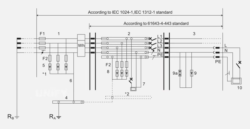
Figure 2-13 TN-C power distribution system graded lightning arrester configuration
TN-S System:
- Similar to TN-C, with separate protective ground and neutral lines, as shown in Figure 2-14.
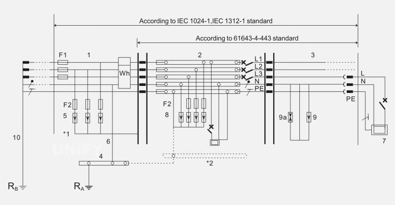
Figure 2-14 TN-S power distribution system graded lightning arrester configuration
TT System:
- Configured with Level 1 and 2 surge protectors, ensuring grounding resistance compliance, as shown in Figures 2-15 and 2-16.
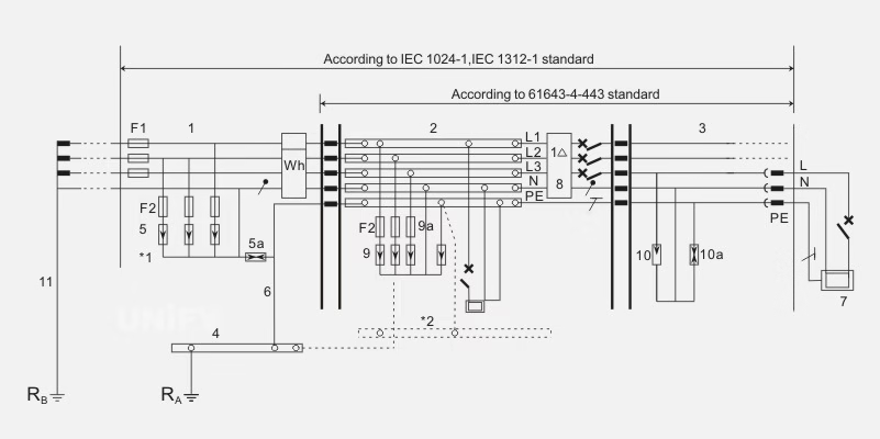
Figure 2-15 TT power distribution system graded lightning arrester configuration (I)
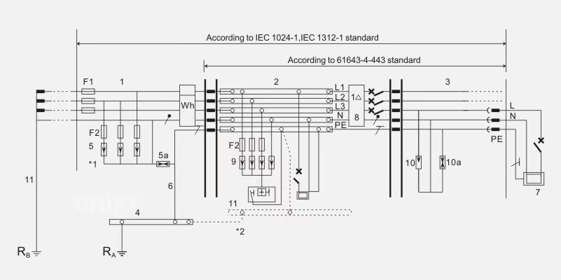
Figure 2-16 TT power distribution system graded lightning arrester configuration (Part 2)
(3) Information Transmission System Lightning Protection
- Characteristics:
- LED displays have low resistance to induced pulse overvoltages, making them susceptible to lightning.
- Induced lightning is more probable than direct strikes, and the system’s multiple interfaces and long lines increase coupling risks.
- Protection Measures:
- Use shielded soft cables, preferably laid underground. Overhead lines should be grounded at each pole, with metal pipes and cables also grounded.
- For underground cables, use metal pipes with a minimum burial length of 15m, connecting the cable’s metal sheath and pipe to the lightning grounding device.
(4) Control System Lightning Protection
- Control Room Protection:
- Buildings housing control rooms should have lightning rods, bands, or nets per GB 50057.
- Metal pipelines entering the control room should connect to the lightning grounding device, and overhead cables should have surge protectors at entry points.
- Equipotential Bonding:
- Install an equipotential bonding busbar in the control room, connecting to lightning grounding, PE lines, equipment grounding, and anti-static grounding.
- Surge Protection:
- Install surge protectors on video transmission lines before entering the display or control room.
- Grounding Requirements:
- Dedicated grounding resistance ≤4Ω; integrated grounding network ≤1
LED Display Electrostatic Discharge (ESD) Protection
(1) Electrostatic Discharge (ESD) Definition
ESD is the abbreviation for Electro-Static Discharge, meaning the discharge of static electricity. ESD pulses have a wide bandwidth, short rise time, and high peak energy. In dry weather, when one person touches another, they may feel a shock; when removing a synthetic fiber sweater in the dark, bright sparks may be visible. These are ESD phenomena.
The definition of electrostatic discharge is: the transfer of charge between objects with different electrostatic potentials due to proximity or direct contact. Charges remain stable under the following two conditions: (1) When trapped on conductive but electrically insulated objects, such as a metal screwdriver with a plastic handle. (2) When residing on an insulating surface (e.g., plastic) without flowing.
Interactions between materials (e.g., friction, contact, induction, or conduction) cause materials to gain or lose electrons, disrupting electrical balance and accumulating charges. The accumulation of charges results in static electricity on the material’s surface. When charges accumulate to sufficient strength, they may discharge, breaking down surrounding materials to achieve a new electrical balance. This rapid neutralization of static charges is called electrostatic discharge. Due to its fast rate and typically low discharge resistance, it often causes instantaneous large currents, potentially exceeding 20A. Such discharges, if passing through integrated circuits, can cause significant damage.
ESD is a discipline studying the generation and dissipation of static electricity, electrostatic discharge models, and effects such as thermal (spark) effects and electromagnetic effects (electromagnetic interference, EMI, and electromagnetic compatibility, EMC). Internationally, devices used for electrostatic protection are commonly referred to as “ESD” devices. In China, these are often called ESD circuit protection devices or static suppressors. ESD has multiple models to describe how devices are damaged, such as the Human Body Model (HBM), Charged Device Model (CDM), and Field-Induced Model.
(2) ESD Damage Mechanisms
Component breakdown caused by electrostatic discharge is the most common and severe hazard in the electronics industry, particularly in electronic product manufacturing. Electrostatic discharge can cause hard breakdown or soft breakdown in devices. Hard breakdown results in permanent failure, such as open or short circuits at the device’s output or input. Hard breakdown causes instantaneous thermal damage within the chip, secondary breakdown of metal bonds, melting of dielectrics, or surface breakdown, ultimately leading to complete and permanent failure of the integrated circuit. When the electrostatic discharge energy reaches a certain level, it can cause the integrated circuit to explode, completely burning out the chip and exposing it, potentially causing personal injury or equipment failure. Hard breakdown characteristics are evident and can generally be detected before the assembled component or circuit board is delivered.
Soft breakdown (soft failure) causes performance degradation or reduced parameter metrics without complete failure, creating hidden risks that are difficult to detect during final quality inspections. Circuits damaged by static electricity may exhibit latent damage, leading to parameter changes, quality degradation, and reduced lifespan. Over time, with changes in temperature, time, or voltage, various faults may emerge, preventing normal operation—this is known as soft failure. If the damaged chip is part of critical control systems, such as network control centers, automatic broadcast control systems, production scheduling control centers, electronic warfare command systems, automatic navigation systems, or rocket launch control systems, the consequences can be unpredictable. Latent damage poses a greater risk, causing more severe direct or indirect losses. Soft breakdown is difficult to detect and has hidden characteristics, making it more hazardous. Data indicates that 90% of ESD-induced device damage is latent soft breakdown, while 10% is immediate failure.
Soft breakdown can degrade device performance and lower parameter metrics, creating fault risks. Since soft breakdown may cause intermittent circuit performance (due to reduced metrics), it is hard to detect and causes significant trouble during operation and fault diagnosis. Devices with soft breakdown may still function with issues, showing no fundamental performance changes and potentially passing factory inspections, but they are prone to further failures. Multiple soft breakdowns can lead to hard breakdown, causing abnormal equipment operation.
ESD occurs frequently in electronic equipment, generating potentially destructive voltages, currents, and electromagnetic fields during discharge. Due to the fast discharge rate and low discharge resistance, instantaneous large currents are common, which can burn out related components if passing through integrated circuits.
ESD generates strong peak pulse currents with rich high-frequency components, with frequencies potentially exceeding 1GHz. These high-frequency pulses make PCB traces highly effective receiving antennas, inducing high-level noise.
ESD interferes with circuits in two ways: one is direct damage through conducted currents, and the other is interference from electromagnetic fields coupled through capacitance, inductance, or spatial radiation.
The field generated by ESD currents can penetrate equipment directly or couple through holes, gaps, or input/output cables to sensitive circuits. As ESD currents flow through the system, they excite the paths they traverse, generating radiation waves with wavelengths ranging from a few centimeters to hundreds of meters. This radiated energy produces electromagnetic noise that can damage electronic equipment or interfere with its operation.
If the voltage or current induced by ESD exceeds the circuit’s signal level, it may cause malfunctions or even insulation breakdown, triggering larger currents and ultimately burning out related components. In high-impedance circuits, where currents are small, capacitive coupling dominates, and ESD-induced voltages affect signal levels. In low-impedance circuits, inductive coupling dominates, and ESD currents cause device failure. The two main ESD damage mechanisms are: (1) Thermal failure due to heat generated by ESD currents. (2) Insulation breakdown due to high ESD voltage, triggering larger currents and further thermal failure.
Both types of damage may occur simultaneously in an electronic device. For example, insulation breakdown may trigger large currents, leading to further thermal failure. In addition to causing circuit damage, electrostatic discharge can easily interfere with electronic circuits. ESD interference occurs in two forms: conducted interference and radiated interference.
ESD failure can be permanent or temporary. If the voltage or current generated during contact or conducted discharge is too high, it may cause permanent device damage, such as when touching a circuit in winter, rendering the equipment unusable. In some cases, smaller circuit noise may cause occasional abnormal results without damaging the equipment, known as temporary ESD failure.
Electromagnetic pulses from electrostatic induction and discharge also pose risks, with frequency bands ranging from hundreds of kHz to tens of MHz and levels up to tens of millivolts, capable of damaging static-sensitive devices (SSDs). With increasing integration, smaller sizes, finer photolithographic lines, narrower line spacing, and the use of new materials with low anti-static properties, the electrostatic resistance of integrated circuits has significantly decreased. Some believe that integrated circuits with ESD protection are immune to static damage. However, while protection circuits provide some defense, they can still be significantly damaged when exposed to thousands of volts of static electricity in human or work environments. All integrated circuits are static-sensitive, differing only in their threshold voltage tolerance. Human-perceptible electrostatic discharge occurs above 2500V, so reducing static to imperceptible levels does not eliminate the risk of damage to electronic equipment. Therefore, ESD protection should focus on comprehensive prevention to mitigate risks proactively.
(3) Characteristics of ESD Damage to LED Displays
The characteristics of ESD damage to LED displays are as follows: (1) Concealment: The human body cannot perceive static electricity unless discharge occurs, but even then, there may be no shock sensation, as human-perceptible ESD voltage is 2–3kV, making static electricity concealed. (2) Latency: Some electronic components show no significant performance degradation after ESD damage, but repeated discharges cause internal damage, creating hidden risks, making ESD damage latent. (3) Randomness: From production to failure, a component is constantly at risk from static electricity, which is generated and causes damage randomly. (4) Complexity: Analyzing ESD-damaged components is time-consuming, labor-intensive, and costly due to the fine, delicate, and microscopic structure of electronic products. It often requires high-precision tools like scanning electron microscopes. Even so, distinguishing ESD damage from other failure causes is challenging, often mistaken for early failure or unknown failure. Before fully understanding ESD damage, it is often misattributed, masking the true cause, making ESD damage analysis complex.
(4) ESD Protection Device Selection Considerations
In the lightning protection design of LED display information transmission systems, selecting appropriate ESD protection devices is critical, ensuring compatibility with the system. Key factors for selecting ESD protection devices for LED display information interfaces include:
- Surge forms that may be induced on the information transmission line (e.g., waveform, time parameters, and maximum peak value).
- Critical breakdown voltage of the information interface circuit under simulated lightning impact.
- Data signal level of the information interface under normal operating conditions.
- Residual voltage parameters of the ESD protection device under simulated lightning impact.
- Impact resistance of the ESD protection device.
- Operating frequency of the information transmission system.
- Interface type of the information interface.
- Operating voltage of the information interface.
(1) ESD Protection Device Selection for Ordinary Data Lines: Ordinary data lines are highly susceptible to ESD impact, leading to data disruption, making ESD protection devices essential. For example, the typical application circuit for NXP Semiconductor’s PESDxS2UT is shown in Figure 2-17.
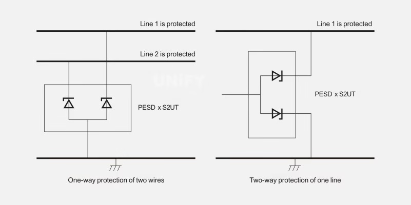
Technical parameters of commonly used ESD protection devices for ordinary data lines are shown in Table 2-1.
| Manufacturer | Model | Number of Protected Lines | Max Reverse Leakage Current (IR, μA) | Max Reverse Working Voltage (URwM, V) | Junction Capacitance (Cp, pF) | Max ESD Voltage (UesD, kV) |
|---|---|---|---|---|---|---|
| NXP | PESD3V3S2UT | 2 | 2 | 3.3 | 207 | 30 |
| NXP | PESD3V3L1BA | 1 | 2 | 3.3 | 101 | 30 |
| NXP | PESD3V3S1UB | 1 | 0.05 | 24 | 23 | 23 |
| ON | NP0080TA | 2 | 0.5 | 8 | 4 | 8 |
| ON | NUP412VP5 | 4 | 0.5 | 6 | 6.5 | 30 |
(2) ESD Protection Device Selection for USB Interfaces: USB ports are hot-swappable systems, highly susceptible to ESD from user handling or air discharge, which can occur a few inches from the conductive surface of the USB port. Electrostatic discharge can damage USB interfaces, causing “hard damage” or component failure in USB integrated circuits.
New low-capacitance transient suppression diode arrays are suitable for ESD protection in USB2.0 or USB1.1 interfaces, offering excellent filtering functions. For example, the typical application circuit for ON Semiconductor’s NUP4114UPXV6 is shown in Figure 2-18.
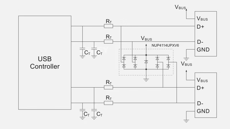
Figure 2-18: NUP4114UPXV6 Typical Application Circuit in USB Systems
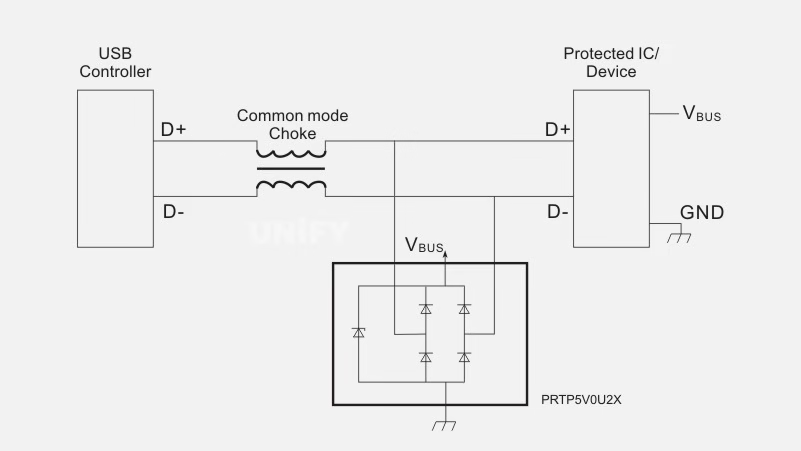
The typical application circuit for NXP Semiconductor’s PRTP5V0U2X is shown in Figure 2-19.
Technical parameters of commonly used ESD protection devices for USB systems are shown in Table 2-2.
Table 2-2: Technical Parameters of ESD Protection Devices for USB Circuits
| Manufacturer | Model | Number of Protected Lines | Max Reverse Leakage Current (IR, μA) | Max Reverse Working Voltage (URwM, V) | Junction Capacitance (Cyp, pF) | Max ESD Voltage (UEsD, kV) |
|---|---|---|---|---|---|---|
| NXP | PRTP5V0U2X | 2 | 0.1 | 3 | 1 | 8 |
| NXP | PRTP5V0U2AX | 2 | 0.1 | 3 | 1.8 | 12 |
| NXP | PRTP5V0U4D | 4 | 0.1 | 3 | 1 | 8 |
| ON | NUP4114UPXV6 | 4 | 1.0 | 5.0 | 0.8 | 8 |
| ON | NUP4202W1 | 4 | 5.0 | 5.0 | 3.0 | 8 |
| ON | NUP2202W1 | 2 | 5.0 | 5.0 | 0 | 8 |
(3) ESD Protection Device Selection for CAN Bus: The CAN bus is widely used in various short-distance data transmission systems. In CAN bus data transmission networks, ESD pulses are a major cause of network communication issues and equipment damage. When designing CAN bus circuits, miniature packaged CAN-specific ESD protection components can be selected to suppress ESD and other destructive voltage spikes, significantly enhancing system reliability.
For example, the typical application circuit for NXP Semiconductor’s PESD1CAN is shown in Figure 2-20.
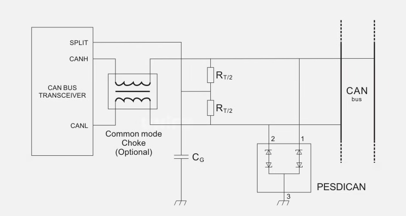
Figure 2-20: Typical Application Circuit of ESD Protection Device in CAN Bus
Dedicated CAN bus ESD protection devices, such as NXP’s PESD1CAN and ON Semiconductor’s NUP2105L, meet 8kV contact discharge and 16kV air discharge ESD test standards. Technical parameters of commonly used ESD protection devices for CAN bus are shown in Table 2-3.
Table 2-3: Technical Parameters of Commonly Used ESD Protection Devices for CAN Bus
| Manufacturer | Model | Number of Protected Lines | Max Reverse Leakage Current (IR, μA) | Max Reverse Working Voltage (URwM, V) | Junction Capacitance (C, pF) | Max ESD Voltage (UesD, kV) |
|---|---|---|---|---|---|---|
| NXP | PESD1CAN | 2 | 0.05 | 24 | 11 | 23 |
| ON | NUP2105L | 2 | 0.1 | 24 | 30 | 30 |
| ON | NUP1105L | 2 | 0.1 | 24 | 30 | 30 |
(4) ESD Protection Device Selection for DVI/HDMI Interfaces: DVI/HDMI interfaces require low-capacitance ESD protection devices to ensure high-speed data transmission and signal integrity. Typically, for video applications with data rates above 480Mbit/s, ESD protection devices with capacitance around 3pF are used. DVI and HDMI interfaces are commonly used for digital video, audio, and display connections. Due to high-frequency signal processing requirements (up to 1.6GHz), these data lines require extremely low line capacitance. Philips provides unique ESD protection devices with 1pF line capacitance, meeting the 8kV contact discharge IEC 61000-4-2 standard. For example, the connection diagram for NXP’s NXPESD device in DVI/HDMI interface protection is shown in Figure 2-21.
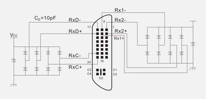
Figure 2-21: NXPESD Device Connection Diagram in DVI/HDMI Interface Protection
The new DVIULC6-4SC6 is a monolithic dedicated discrete device with ultra-low line capacitance (typical 0.6pF, maximum 1pF for DVI/HDMI applications), providing 15kV ESD protection for high-speed interfaces without compromising signal integrity. It offers complete rail-to-rail protection for four data lines and the power rail.
The DVIULC6-4SC6 exceeds IEC 61000-4-2 Level 4 requirements, achieving up to 15kV contact discharge, while most similar products only guarantee 8kV. In addition to significantly lower line capacitance (0.6pF vs. 3pF), DVIULC6-4SC6 provides better impedance matching (0.015pF vs. 0.04pF), minimizes path imbalance and crosstalk (0.007pF vs. 0.13pF), and offers an ultra-high cutoff frequency (5.5GHz). The DVIULC6-4SC6 uses a compact SOT23-6L package.
LED Display Installation
1.LED Display Cabinet Calculation Method
(1) Indoor LED Display Module Cabinet Calculation Method
(1) Given Specific Data for LED Display (Length, Width, Area)
Example 2-1: The LED display specification is a φ5 (pixel diameter) screen, with a length of 5.8m and a width of 2.6m.
The unit board specification for a φ5 screen is 488×244mm, with a resolution of 64×32. The number of unit boards is calculated using the formula:
mnB = L₁B₁ / L₂B₂ (2-5)
Where:
- m = number of boards used for the screen length
- n = number of boards used for the screen width
- L₁ = planned LED display screen length
- B₁ = planned LED display screen width
- L₂ = unit board length
- B₂ = unit board width
Calculations:
L₁ = 5.8m × 1000 ÷ 488 = 11.89 ≈ 12
B₁ = 2.6m × 1000 ÷ 244 = 10.65 ≈ 11
The actual screen size is calculated using the formula:
LsBs = L₂B₂ × LB (2-6)
Where:
- Ls = actual LED display screen length
- Bs = actual LED display screen width
- L₂ = unit board length
- B₂ = unit board width
- L = number of boards used for screen length
- B = number of boards used for screen width
Calculations:
Ls = 488 × 12 = 5856mm = 5.856m
Bs = 244 × 11 = 2684mm = 2.684m
Screen area S = 5.856 × 2.684 = 15.72m²
Typically, the outer frame size of the LED display is based on the screen size, with an additional 5–10cm added to each side.
The screen resolution is calculated using the formula:
ε = k × λ (2-7)
Where:
- ε = screen resolution
- k = number of boards used
- λ = resolution of the unit board
Calculation:
ε = (12 × 64) × (11 × 32)
(2) Given Only the LED Display Area, No Length or Width
Example 2-2: The LED display area S is 9m², with a specification of φ5 (pixel diameter). If only the area is provided, the length and width need to be calculated. A length-to-width ratio of 4:3 or 16:9 is typically used for better visual effect. Using a 4:3 ratio as an example, the theoretical screen length and width are calculated as follows:
L = √(4/3 × S) (2-8)
B = √(3/4 × S) (2-9)
Calculations:
L = √(4/3 × 9) = 3.46m
B = √(3/4 × 9) = 2.60m
After calculating the length and width, other calculations can follow the method in Example 2-1.
(2) Outdoor LED Display Calculation Method
(1) Given Specific Data (Length, Width)
Example 2-3: An outdoor full-color P20 LED display has dimensions of 10m length and 6m width. The unit cabinet specification is 1280mm × 960mm, with a resolution of 64 × 48. The number of cabinets for length or width is calculated using the formula:
LxBx = L₁B₁ / LDBD (2-10)
Where:
- Lx = number of cabinets used for screen length
- Bx = number of cabinets used for screen width
- L₁ = planned LED display screen length
- B₁ = planned LED display screen width
- LD = unit cabinet length
- BD = unit cabinet width
Calculations:
Lx = 10m × 1000 ÷ 1280 = 7.8123 ≈ 8
Bx = 6m × 1000 ÷ 960 = 6.25 ≈ 6
The actual screen size is calculated using the formula:
LsBs = LDBD × mn (2-11)
Where:
- m = number of cabinets used for screen length
- n = number of cabinets used for screen width
Calculations:
Ls = 1280 × 8 = 10240mm = 10.24m
Bs = 960 × 6 = 5760mm = 5.76m
S = 10.24 × 5.76 = 58.9824 ≈ 58.98m²
The screen resolution ε is calculated using the formula:
ε = λxL × L₁ × λxB × B₁ = 64 × 10 × 48 × 6 (2-12)
Where:
- ε = screen resolution
- λxL = cabinet resolution length
- λxB = cabinet resolution width
Example 2-4: An outdoor full-color P16 LED display has dimensions of 15m width and 12m height. First, determine the actual width and height, then calculate the LED display area.
Calculations:
LED display actual width = 15000 / 256 = 58.59 ≈ 59 × 256 = 15.104m
LED display actual height = 12000 / 128 = 93.75 ≈ 94 × 128 = 12.032m
LED display area = 15.104 × 12.032 = 181.73m²
(2) Given Only the Screen Area, No Length or Width
Example 2-5: An outdoor full-color P20 LED display has an area of 50m². If only the area is provided, the length and width need to be calculated. A length-to-width ratio of 4:3 or 16:9 is used for optimal display effect. Using a 4:3 ratio as an example, calculate the theoretical length and width as follows:
L = √(4/3 × S)
B = √(3/4 × S)
After calculating the length and width, other calculations can follow the method in Example 2-3.
Example 2-6: An outdoor full-color P16 LED display has an approximate area of 100m². Determine the actual width and height, then calculate the actual area. Before calculating, decide whether to use a 16:9 or 4:3 ratio.
For a 16:9 LED Display:
Set the display width as X, then the height is 9/16X.
Solve using the equation:
9/16X² = 100
X = 13.3334m
Thus, LED display width = 13.3334m, height = 7.5m.
Calculations:
Width = 13333.4 / 256 = 52.083 ≈ 52
Actual width = 52 × 256 = 13.312m
Height = 7500 / 128 = 58.59 ≈ 59
Actual height = 59 × 128 = 7.552m
Actual area = 13.312 × 7.552 = 100.53m²
For a 4:3 LED Display:
Set the display width as X, then the height is 3/4X.
Solve using the equation:
3/4X² = 100
X = 11.5468m
Thus, LED display width = 11.5468m, height = 8.660m.
Calculations:
Width = 11546.8 / 256 = 45.1 ≈ 45
Actual width = 45 × 256 = 11.520m
Height = 8660 / 128 = 67.656 ≈ 68
Actual height = 68 × 128 = 8.704m
Actual area = 11.520 × 8.704 = 100.27m²
2.LED Display Assembly Steps
When assembling an LED display, first join the cut profiles to form the outer frame. Common profiles in the market are square or round, but the assembly method is the same. After assembling the outer frame, place the unit boards within the frame (the grooved side of the frame is the front). The back strip installation must be precise to avoid errors, as a single mistake may require reworking the entire setup. Before fabrication, determine the outer frame size. Using a common 3.5×90 profile and a P10 unit board (display size of 2×5 boards) as an example, the method to determine the outer frame is as follows:
(1) Determine the unit board dimensions, accurate to millimeters. For a P10 unit board, the size is 16cm × 32cm.
(2) Calculate the net dimensions of the unit boards for height and width:
Height = 2 boards × 16cm = 32cm
Width = 32cm × 5 boards = 160cm
(3) Subtract 4mm from the calculated net dimensions. For 32cm × 160cm, the aluminum profile dimensions should be:
(32cm – 4mm) × (160cm – 4mm) = 31.6cm × 159.6cm
31.6cm and 159.6cm are the actual aluminum profile dimensions. For screen lengths exceeding 3m, subtract 5mm.
(4) Connect the corners and cut aluminum profiles with self-tapping screws, clean debris, and place the frame face down. Arrange the unit boards correctly, ensuring the direction is not reversed. The side with pins must face the aluminum profile. Attach magnetic support pillars to the unit boards and insert magnetic pieces into the pillar grooves.
(5) Measure and cut the required length for the light steel keel, place it on the magnets, ensuring the magnets are centered to avoid deviation.
(6) Secure the keel to the frame with self-tapping screws.
(7) Connect the unit boards with ribbon cables in a bridge pattern, ensuring no twisting of the cables.
(8) Fix the power supply to an appropriate position inside the profile, typically at the bottom, insulated from the unit boards.
(9) Connect the power lines. Although the LED display operates at low voltage, the current is high, requiring separate power circuits for the unit boards. A P10 unit board has a rated current of 4A, so a 40A power supply can support ten unit boards. Divide the unit boards into three groups (one group with four boards) and use three power circuits for convenience in wiring. The power supply for unit boards is connected in parallel: positive to positive (VCC, +5V, +V), negative to negative (GND, COM, -V). Ensure correct polarity to avoid damaging the unit boards.
(10) Place the control card at the input end of the unit board, directly powered by a 5V supply from the power source. The control card pins have a specific order and must be connected according to the arrow markers on the unit board input.
(11) Connect the control card and unit boards. The control card pins are marked with a white “A” letter, as are the unit board input ends. Connect the two “A” markers correctly with a ribbon cable in parallel.
After completing the above steps, clean debris inside the LED display to prevent conductive materials like aluminum or iron shavings or wire ends from causing damage. After cleaning, prepare the data lines before powering on, as the control card cannot display properly without updated data lines. Typically, LED displays require two of the following three data lines:
(1) Extension Cable: Required for every LED display to extend the control card’s data interface to the outside (due to the rear cover). Materials include a three-core wire, one DB9 pin, and one DB9 socket. The DB9 pin and socket are marked with numbers 1–9. Connect only 2, 3, and 5:
- DB9 pin 2 to DB9 socket 2
- DB9 pin 3 to DB9 socket 3
- DB9 pin 5 to DB9 socket 5
Weld securely, then attach the plastic shell to the pin end.
(2) Crossover or Parallel Cable: Similar to the extension cable, but parallel cables use two DB9 sockets with plastic shells. For crossover cables, connect pin 2 to pin 3 of the other end, pin 3 to pin 2, and pin 5 to pin 5. The choice between crossover or parallel cables depends on the control card model.
After completing the wiring, thoroughly inspect and test the power and data lines to ensure accuracy before proceeding to power-on and system debugging.
3.LED Display Frame and Accessory Fabrication
(1) LED Display Frame Fabrication
LED display frames are categorized as embedded installation brackets, simple frames, or stainless steel/aluminum alloy frames.
(1) Embedded Installation Bracket: Depending on the application, frames vary. Embedded installations do not require an outer frame but need a bracket, typically made of lightweight, easy-to-cut aluminum profiles or universal angle iron (perforated right-angle iron bars). Copper pillars on the back of the unit board fix it to the bracket, as shown in Figure 2-22. The bracket should be longer, with reserved holes for mounting the lightbox. Secure the unit boards, control card, and power supply to the bracket, and tie data and 220V power lines to the bracket with nylon ties, knotting them to prevent detachment.
Figure 2-22: Unit Board Mounting Bolts and Copper Pillars
(2) Simple Frame: Use aluminum alloy profiles (e.g., hollow square-section bars). For small screens, unit boards can be fixed directly to the frame if it is strong enough, eliminating the need for a bracket.
(3) Stainless Steel or Aluminum Alloy Frame: Typically, stainless steel frames are simple frames wrapped with a thin stainless steel skin for aesthetics and added value. Fabrication and assembly are usually outsourced to a metalworking factory after determining dimensions.
(2) Accessory Fabrication
(1) Ribbon Cable (Data Cable) Fabrication: Ribbon cables resemble computer chassis data cables but differ in width. Special crimping pliers are used to improve efficiency and quality. Materials include ribbon cable, ribbon cable headers, and caps. For a 16-pin ribbon cable, use a 16-pin cable, header, and cap. Steps:
- Trim the cable end flat with scissors and insert it into the ribbon cable header.
- Place the header in the center of the crimping pliers and press firmly.
- Fold the cable over and install the ribbon cap, which strengthens and protects the cable, as shown in Figure 2-23.
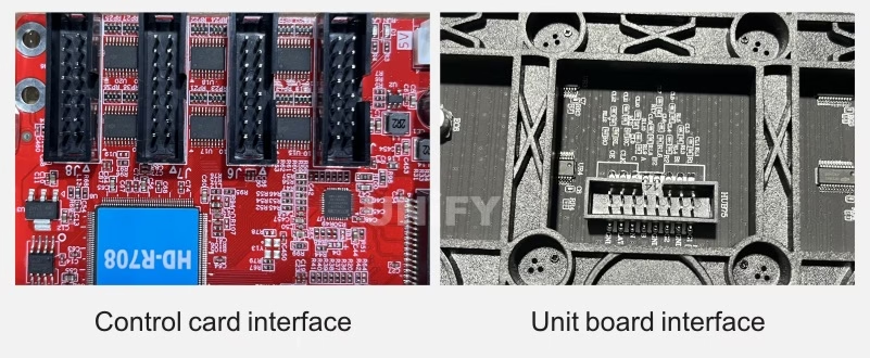
Figure 2-23: Control Card Interface and Unit Board Interface
(2) Conversion Cable Fabrication: The control card interface (e.g., 08 interface) and unit board interface (e.g., P10 unit board with 12 interface) differ. The control card has R1, R2, R3, R4, etc., corresponding to rows 1, 2, 3, 4 of unit boards, respectively, as shown in Figure 2-24.
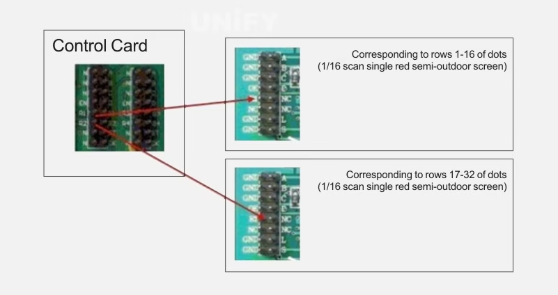
Figure 2-24: Correspondence Between Control Card R1, R2, and Unit Boards
Steps for making a conversion cable using ribbon headers:
- Tear the ribbon into six segments: 1, 5, 1, 1, 4, 4, as shown in Figure 2-25(a).
- Rearrange the torn ribbon and install the ribbon header, as shown in Figure 2-25(b).
- Crimp the ribbon with pliers, as shown in Figure 2-25(c).
- Cross the ribbon and optionally crimp another header, as shown in Figure 2-25(d).
- Cut wires 8, 10, and 12 with a utility knife and scissors, as shown in Figure 2-25(e).
- Mark the direction with an arrow, as shown in Figure 2-25(f), completing the conversion cable.
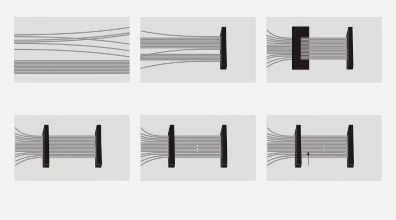
Figure 2-25: Conversion Cable Fabrication Diagram
(a) Tear into segments
(b) Rearrange and install ribbon header
(c) Crimp with pliers
(d) Cross and crimp another header
(e) Cut wires
(f) Mark direction
(3) Power Cable Fabrication: LED display power cables include 220V and 5V cables. The 220V cable connects the switch power supply to the AC input, preferably with a three-pin plug. The 5V DC cable, carrying high current, should use red-black paired copper wires with a core diameter of at least 1mm, with crimped terminals at both ends.
(4) RS232 Cable Fabrication: The RS232 cable connects the computer to the control card, using a DB9 connector and network cable. Connect DB9 pin 5 to the brown wire and pin 3 to the brown-white wire. Secure the cable in the DB9 connector and test continuity with a multimeter. The computer’s serial port is a female socket, so use a male DB9 connector.
4.LED Display Aluminum Profile Clamp Installation and Power Line Connection
(1) LED Display Aluminum Profile Clamp Installation
Clamps adjust the flatness of the display’s front surface. During installation, the side with screw heads faces the installer. Place one iron plate parallel and another perpendicular, insert between two aluminum bars, rotate to align parallel with the front plate, and tighten the screws, as shown in Figure 2-26.
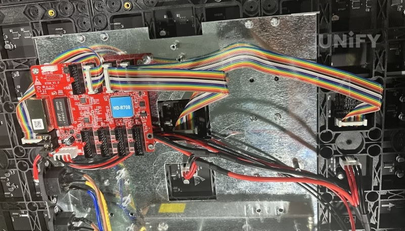
Figure 2-26: Aluminum Profile Clamp Installation Diagram
(2) 220V/5V Power Line Connection
(1) 220V Power Line Connection: Connect switch power supplies in parallel with 220V power lines, attaching each line to the “L” and “N” terminals, as shown in Figure 2-27. After connecting (and confirming correctness), attach to AC or NL terminals, plug in the power, and the power indicator should light up. Measure the voltage between V+ and V- with a multimeter’s DC setting, ensuring it is 4.8–5.1V. Adjust the voltage using a screwdriver on the adjacent knob. To reduce heat and extend lifespan in low-brightness settings, adjust to 4.5–4.8V. After confirming the voltage, disconnect power and continue assembly.
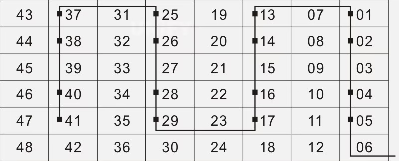
Figure 2-27: 220V Power Line and Switch Power Supply Connection Diagram
LED display power depends on the number of 595 chips. At full brightness, one 595 chip has a maximum power of 0.4A. For text-only displays, it is 0.2A. Since many power supplies’ maximum output is less than rated, and full brightness is rare, the maximum power equals the nominal power. Typically, use dedicated 5V LED display power supplies with 5V/10A–40A ratings.
(2) 5V Power Line Connection: Turn off the power supply, connect V+ to the red wire and V- to the black wire, linking to the control card and LED unit board. The black wire connects to the control card and power supply’s GND, and the red wire connects to the control card’s +5V and unit board’s VCC. Each unit board requires one power line. After wiring, verify connections. Black wires connect to the two “COM” terminals on the switch power supply, and red wires to the two “+V” terminals. The motherboard’s red-black power lines follow the same connection, with one terminal supporting multiple lines, as shown in Figure 2-28. Each switch power supply connects to three driver boards, as shown in Figure 2-29, where “■” represents the switch power supply and “-” represents the 5V power line.
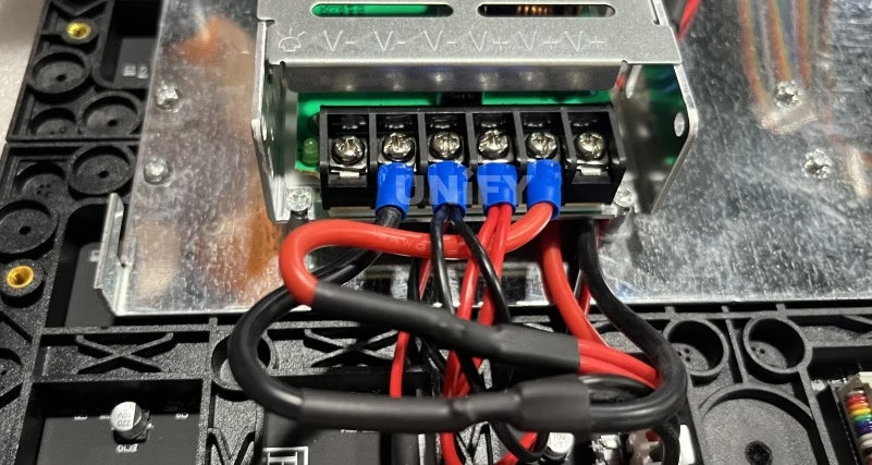
Figure 2-28: 5V Power Line Connection Diagram
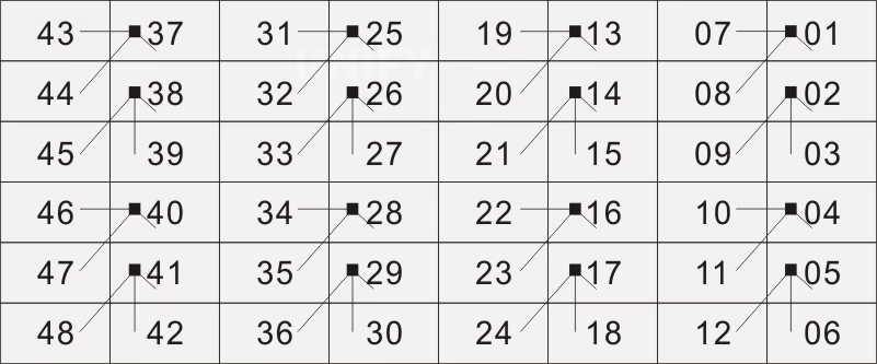
Figure 2-29: Switch Power Supply Connection Diagram
(3) Single-Core Wire and Pin-Hole Terminal Connection: For single-core wires, fold the wire to double thickness and insert into the pin-hole, ensuring the crimping screw secures the middle of the doubled wire. If the wire is too thick, insert a single core, slightly bending it upward before insertion to prevent loosening, as shown in Figure 2-30.
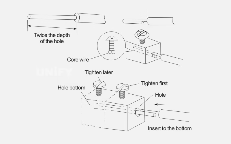
Figure 2-30: Single-Core Wire and Pin-Hole Terminal Connection
(4) Single-Core Wire and Flat-Pressure Terminal Connection: Bend the wire end into a crimping loop (sheep’s eye loop), then secure with a screw. The bending method is shown in Figure 2-31:
- Fold at about 3mm from the insulation root outward.
- Bend into an arc slightly larger than the screw diameter.
- Trim excess wire.
- Shape into a round loop.
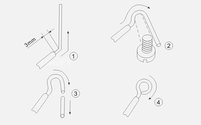
Figure 2-31: Sheep’s Eye Loop Bending Method
(5) Multi-Core Wire and Pin-Hole Terminal Connection: Tighten multi-core wires with pliers to prevent loosening under screw pressure. If the pin-hole is too large, wrap a suitably sized wire tightly around the core to match the hole size before crimping. If too small, trim some strands, retighten, and crimp, as shown in Figure 2-32.
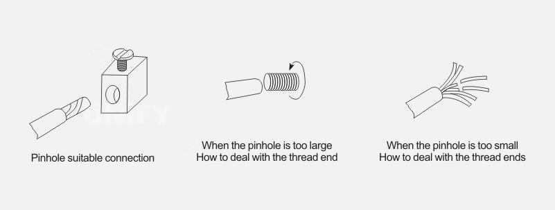
Figure 2-32: Multi-Core Wire End Processing Method
(6) Multi-Core Wire and Flat-Pressure Terminal Connection: The crimping loop fabrication method is as follows:
- Tighten the core at about half the distance from the insulation root, as shown in Figure 2-33(a).
- Fold the tightened core at one-third from the insulation root to the left, then bend into an arc, as shown in Figure 2-33(b).
- When the arc is nearly a circle (one-quarter remaining), fold the remaining core to the right to form a circle and flatten the ends parallel, as shown in Figure 2-33(c).
- Divide the loose cores into three groups (2, 2, 3), bend the first two cores upward perpendicular to the core, leaving space for the washer edge, as shown in Figure 2-33(d).
- Process using the self-wrapping method for seven-core wires, as shown in Figure 2-33(e).
- Final shaping, as shown in Figure 2-33(f).
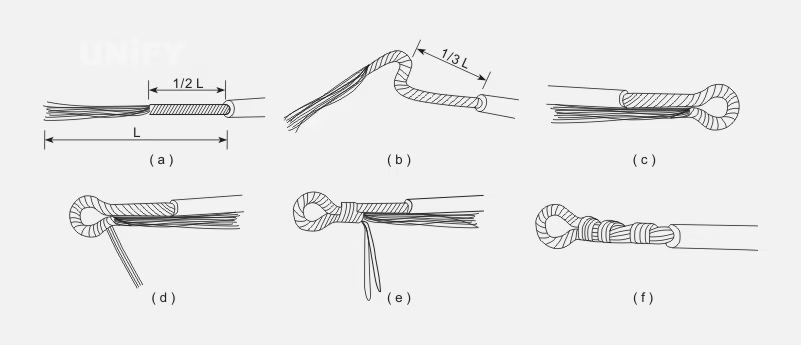
Figure 2-33: Multi-Core Wire and Flat-Pressure Terminal Crimping Loop Fabrication Method
(a) Tighten core
(b) Bend arc
(c) Form circle and flatten ends
(d) Group loose cores
(e) Self-wrap
(f) Final shaping
(7) Flexible Wire and Pin-Hole Terminal Connection:
- Tighten multi-core wires, ensuring no stray strands form burrs, as shown in Figure 2-34(①).
- Fold the core to double thickness per the pin-hole depth, as shown in Figure 2-34(②).
- Wrap the remaining core clockwise around the doubled core tightly, as shown in Figure 2-34(③).
- Trim excess, flatten burrs, insert into the pin-hole, and tighten the screw, as shown in Figure 2-34(④).
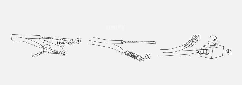
Figure 2-34: Flexible Wire and Pin-Hole Terminal Connection
(8) Improper Wire and Terminal Connections: Eight improper crimping methods are shown in Figure 2-35:
(a) Incomplete crimping loop, small contact area
(b) Overly long wire root, risking short circuits
(c) Overly long excess wire, causing loose contact
(d) Crimping loop too small for screw
(e) Non-round crimping loop, causing poor contact
(f) Overly long excess, risking short circuits or shocks
(g) Half-circle loop, unable to secure
(h) Flexible wire with untwisted burrs, risking short circuits
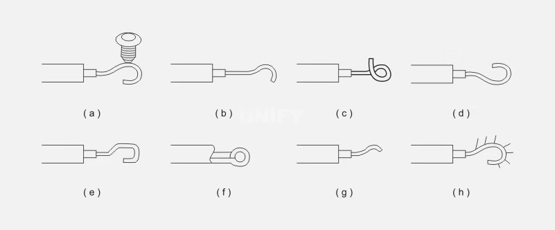
Figure 2-35: Eight Improper Crimping Methods
5.Information Cable Installation and Connection
(1) 26-Pin Flat Cable Installation
Each driver board is connected to its adjacent driver board with two 26-pin cables. Insert one end into the 26-pin double-row pin of the previous driver board and the other end parallel into the 26-pin double-row pin of the adjacent driver board, as shown in Figure 2-36.
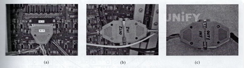
Figure 2-36: 26-Pin Flat Cable Installation Diagram
(2) 60-Pin Communication Cable Connection
The 60-pin communication cable has eight numbered connectors. Connect the 4-1 connector to the 4-1 motherboard, and connect the remaining connectors to their corresponding motherboards, as shown in Figure 2-37(a). Connect the dockable connectors between 4-1 and 8-1, as shown in Figure 2-37(b). The 8-6 connector has an extension connector linked to the “OUT1” end of the communication cable, as shown in Figure 2-37(c).
Figure 2-37: 60-Pin Communication Cable Connection Diagram
(3) Connecting Control Card and Unit Board
When connecting the control card to the unit board with a ribbon cable, ensure the correct connection direction. The unit board has two 16-pin interfaces: one input (near 74HC245/244) and one output. Connect the control card to the input and the output to the next unit board’s input, as shown in Figure 2-38.
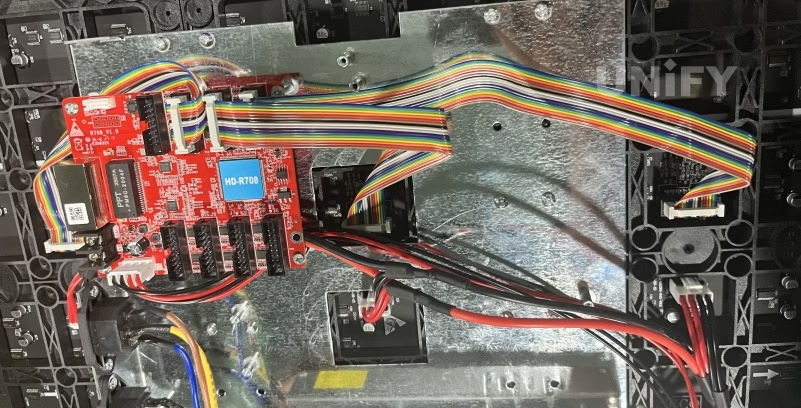
Figure 2-38: Control Card and Unit Board Connection Diagram
For an 08-to-12 interface, wire according to the principle in Figure 2-39 (one 08 interface can lead to two 12 interfaces). Typically, control card data lines R1, G1 correspond to the top 16 rows, and R2, G2 to the bottom 16 rows. For a 32-point display, the control card must support 32 rows. If the control card has only one port, modify wiring as shown in Figure 2-40.
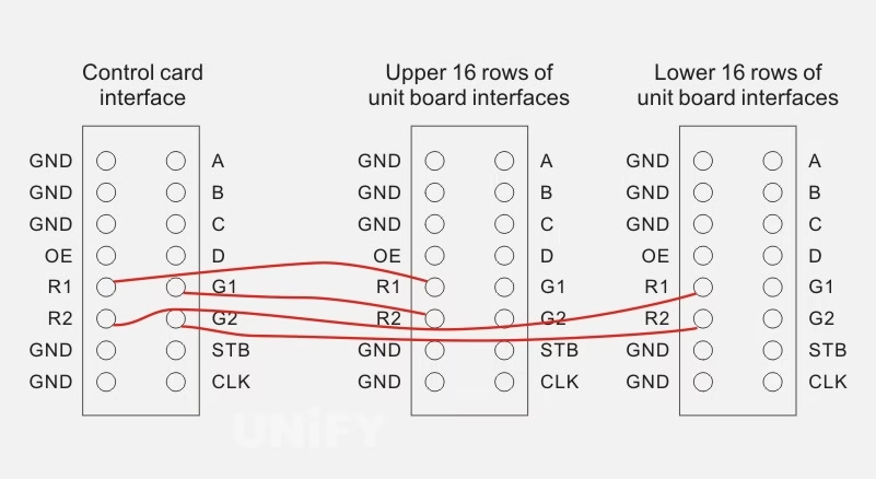
Figure 2-39: Principle Wiring Diagram
Figure 2-40: Modified Wiring Diagram
(4) Connecting RS232 Data Line
Connect one end of the prepared data line to the computer’s DB9 serial port and the other to the control card. Connect DB9 pin 5 (brown) to the control card’s GND and pin 3 (brown-white) to RS232-RX. If the PC lacks a serial port, use a USB-to-RS232 adapter.
(5) RJ-45 Plug Fabrication Method
The RJ-45 plug, commonly called a “crystal head,” is a plastic connector that locks in place to prevent detachment. Its professional term is RJ-45 connector (similar to the RJ-11 telephone interface). Both ends of a twisted pair must have RJ-45 plugs to connect to a network interface card (NIC), hub, or switch for network communication.
The RJ-45 plug cross-section is shown in Figure 2-41, with pins numbered 1–8 from left to right. Common wiring errors include using a one-to-one connection, as shown in Figure 2-42(a), which may work for short distances but fails in busy or high-speed networks. The preferred method, shown in Figure 2-42(b), uses pins 3 and 6 as a twisted pair.
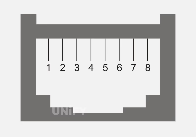
Figure 2-41: RJ-45 Plug (Crystal Head) Cross-Section Diagram
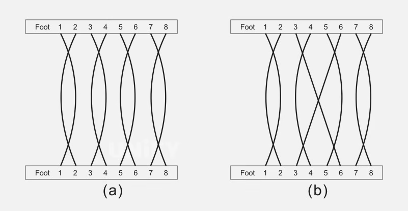
Figure 2-42: Connection Methods
(a) One-to-one connection
(b) Pins 3 and 6 as a twisted pair
The quality of the crystal head is critical, as poor quality (e.g., copper-plated probes) can cause rusting, poor contact, or network failure. Loose plastic latches (often due to deformation) can also cause contact issues.
Following the EIA/TIA-568 standard, RJ-45 network cables have two connection methods: T568A and T568B, as shown in Figure 2-43.
(1) RJ-45 Pin Functions:
Pins 1, 2 for data transmission (TX), pins 3, 6 for data reception (RX), and pins 4, 5, 7, 8 as bidirectional lines. Pins 1–2, 3–6, 4–5, and 7–8 must be twisted pairs.
- For 10M networks, only pins 2 and 6 are needed, so testers show only these lights.
- For 100M networks, pins 1, 2, 3, and 6 are used, so testers show these lights.
- For 1000M networks, all pins (1–8) are used, so testers show all lights.
- (2) T568A Line Sequence Application:
- Used for crossover connections (different wiring at each end: T568A at one end, T568B at the other). Applications include computer-to-computer (peer-to-peer), hub-to-hub, or switch-to-switch connections. The T568A wiring is shown in Figure 2-44:
- Pin 1: White-green
- Pin 2: Green
- Pin 3: White-orange
- Pin 4: Blue
- Pin 5: White-blue
- Pin 6: Orange
- Pin 7: White-brown
- Pin 8: Brown
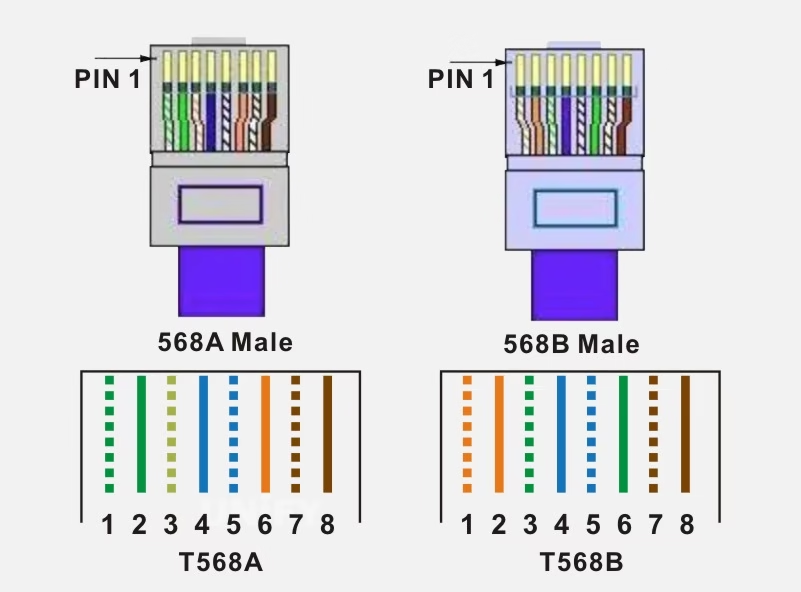
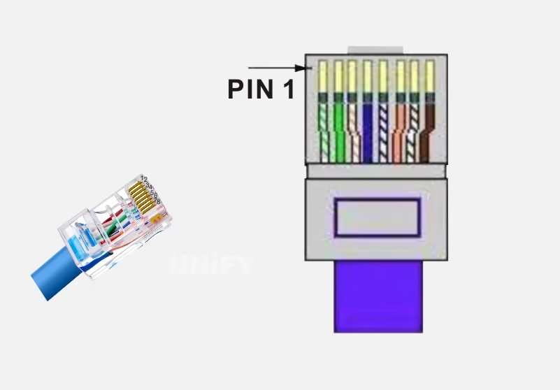
Figure 2-44: T568A Line Sequence for RJ-45 Plug
(3) T568B Line Sequence Application:
- Straight-Through Connection: Both ends use T568B for computer-to-ADSL modem, ADSL modem-to-router WAN port, computer-to-router LAN port, or computer-to-hub/switch.
- Crossover Connection: One end T568B, the other T568A, for computer-to-computer, hub-to-hub, or switch-to-switch connections.
The T568B wiring is shown in Figure 2-45:
- Pin 1: White-orange
- Pin 2: Orange
- Pin 3: White-green
- Pin 4: Blue
- Pin 5: White-blue
- Pin 6: Green
- Pin 7: White-brown
- Pin 8: Brown
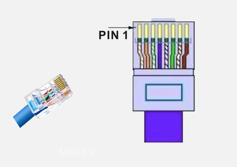
Figure 2-45: T568B Line Sequence for RJ-45 Plug
Pin identification: Hold the plug with the eight gold-plated pins upward and the rectangular cable entry downward, facing the side without the plastic latch. From the left, the pins are numbered 1 to 8.
RJ-45 Plug Fabrication Steps:
- Strip the outer insulation, untwist the four pairs of wires to the same length, straighten them, and arrange according to T568B (white-orange, orange, white-green, blue, white-blue, green, white-brown, brown), as shown in Figure 2-46(a). Trim the ends to 14mm, ensuring no crossover for at least 10mm from the end, as shown in Figure 2-46(b).
- Untwist the four pairs, arrange in order (1–2, 3–6, 4–5, 7–8), and ensure the cable remains parallel for at least 8mm inside the sleeve to prevent damage. The crossover section forms an oval.
- Untwist wires to align parallel in the correct order, with wire 6 crossing wires 4 and 5 within 4mm of the sleeve.
- Trim wires (ends must be flat, no burrs) to 14mm, with no crossover for 10±1mm.
- Insert wires into the crystal head, ensuring they reach the front end, with the flat section extending at least 6mm beyond the sleeve, as shown in Figure 2-47.
- Crimp the crystal head, ensuring the eight blades pierce the insulation and contact the copper cores. The blades should be lower after crimping, as shown in Figures 2-48 and 2-49.
- Visually inspect that the eight gold-plated blades are inserted and level.
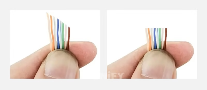
Figure 2-46: Stripping Outer Insulation
(a) Stripped and arranged twisted pairs
(b) Trimmed twisted pairs
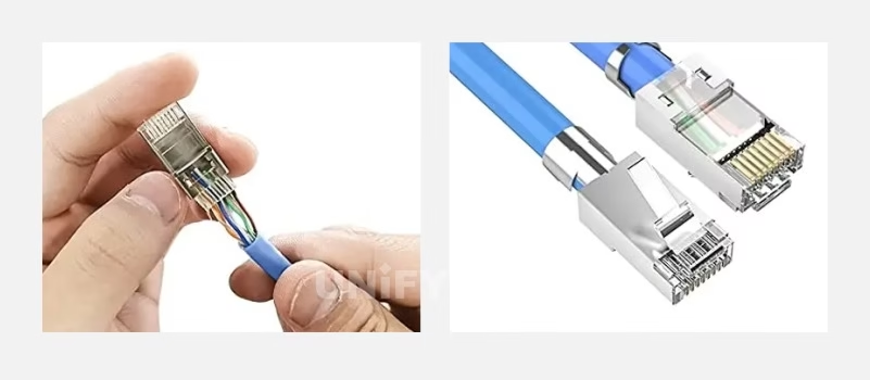
Figure 2-47: Inserting Wires into Crystal Head Diagram
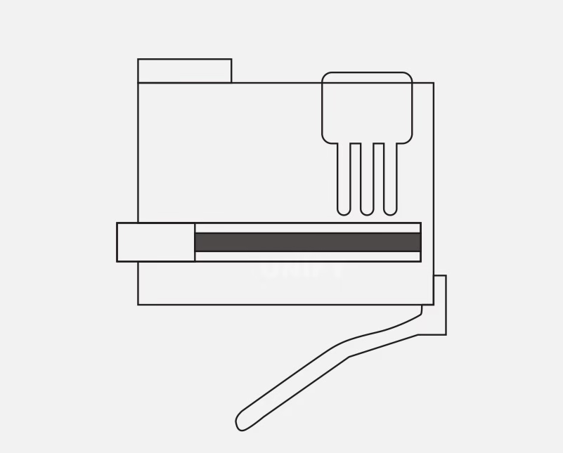
Figure 2-48: RJ-45 Head Blade Position Before Crimping
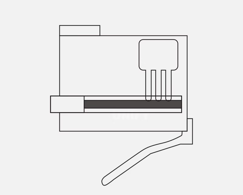
Figure 2-49: RJ-45 Head Blade Position After Crimping
6. Precautions for installing LED display screens and pre-startup inspections
(1) Precautions for installing LED display screens
The following points should be noted when installing LED display screens:
(1) Determination of frame material size: The frame size is determined according to the final product specifications and the unit board size. When cutting, the width of the aluminum alloy frame should be considered. The upper and lower horizontal blocks should be reduced by twice the frame width, and the vertical blocks should also be reduced by twice the frame width.
(2) Corner connection: Use plastic connectors at the corners and fix them with four self-tapping screws (one each at the top and bottom). After the frame assembly is completed, place the unit board.
(3) Unit board placement: Arrange according to the unit board specifications (such as 4.8×0.48m unit board, 15 horizontal blocks and 3 vertical blocks), and ensure that the arrow directions on the unit boards are consistent.
(4) Screw installation: Use special screws to fix the unit board and install the magnetic column. The screws are placed close to the inner row of frames to facilitate the fixing of the back strip.
(5) Back panel installation: Pre-drill holes in the back panel (two at each end, a total of four), and fix them to the frame with self-tapping screws so that the magnetic column is adsorbed on the back panel. (6) Data cable connection: Connect one end of the data cable to the right socket of the left unit board, pass it through the backplane, and connect it to the left socket of the adjacent right unit board. Repeat this operation until all unit boards are connected.
(7) Power cable connection: Connect the red wire to the ACC terminal of the unit board and the black wire to the GND terminal. Make sure the connections are correct.
(8) Power box and wiring: The 40A power box supports up to 12 unit boards, but to reduce heat, connect eight. The power box has nine terminals: 1-2 for 220V AC, 3 for ground, 4-6 for 5V positive, and 7-9 for 5V negative.
(9) Control card wiring: Match the number of control card connections with the number of unit board rows. Connect the colored end of the data cable to the OE terminal of the control card and the OE terminal of the unit board. Make sure not to connect them reversely. Connect the RS-232 cable to the control card and connect the power supply of the control card to the 5V power supply of the power box. Make sure the polarity is correct to avoid burning the control card. (10) Power cord connection: Connect the power cord to terminals 1 and 2 of the power box, making sure that all power boxes used are connected. Connect the two-pin plug at the other end to connect the power supply.
(2) Pre-power-on inspection and power-on test
(1) Check:
Make sure that all adjacent driver boards (except between the fourth and fifth bars) are connected with 26-pin cables and match the double-row pins.
Confirm that all 5V power cable black wires are connected to the “COM” terminal and the red wires are connected to the “+V” terminal.
Confirm that all eight numbered 60-pin connectors are connected to the corresponding motherboards.
(2) Power-on test: Connect 220V AC power. Under normal circumstances, the power indicator light is on, the control card indicator light is on, and the LED display shows the content. If it is not normal, please disconnect the 220V power supply and check the integrity of the power cord and connector. If it is normal, use the control card software to update the content and set the parameters. Use a computer to send data to the LED display. For specific operations, please refer to the LED display manual.
.
7.LED Display Computer Requirements and Software/Hardware Installation
(1) LED Display Computer Requirements
The host should be a standard commercial computer or compatible machine with:
- Hard disk space of 40GB or more
- Memory of 1MB or more
- Motherboard with AGP and PCI slots
- Operating system: Windows 2000, XP, or 7
LED display system configuration (per shipping list):
- DVI graphics card (e.g., Colorful Red, installed in the computer)
- DVI main control card (data acquisition and transmission card, installed in the computer)
- Scan board (data reception and display driver card, with 1–2 hub boards, installed behind the display)
- DVI cable, RS-232 serial cable
- PCTV card (optional)
(2) Hardware Installation
Steps:
- Insert the DVI graphics card into the motherboard’s AGP slot and install its driver.
- Insert the data acquisition card into an empty PCI slot.
- Connect the data acquisition card to the graphics card with a DVI cable.
- Connect the control line to the RS-232 serial port (optional).
- Connect the network cable to the receiving card.
- Connect the display driver card to the hub board with a 50-pin flat cable, ensuring one-to-one correspondence.
- Verify connections before setting up or powering on for debugging.
(3) Software Installation
(1) Graphics Card Driver Installation: Insert the graphics card driver CD into the drive for automatic installation. Follow prompts to install DirectX 8.1, then the driver, and finally the control panel.
(2) Playback Software: Dedicated LED display software (e.g., LED Studio, LEDSHOW4.0) meets most display requirements. Insert the accompanying software CD, copy or install all programs to the computer.
(3) PCTV Card Software: Insert the PCTV card driver CD for automatic installation, following prompts. This hardware and software support external signal sources like VCD, DVD, and TV.
(4) LED Display Operation and Precautions
(1) Power-On Sequence:
- Turn on the computer monitor, then the computer host. Ensure the graphics card settings are correct (incorrect settings cause a black screen). Open the control software and set basic pixel size and display area (this does not affect the display).
- Start the LED control panel, open the editing software, load the edited file, and run the program list.
- Turn on the dedicated LED display switch to power the screen (the screen may flicker regionally upon powering, indicating activation).
(2) Power-Off Sequence:
- Turn off the LED display’s dedicated power switch, exit the editing software, and close all programs.
- Shut down the computer (shutting down the computer before the display prevents high-brightness spots that reduce lifespan).
- Disconnect all power sources connected to the LED display equipment.
(3) Operation Precautions:
- Strictly follow the power-on/off sequence.
- Do not hot-plug system boards or connected devices during operation.
- The dedicated computer should not run games or unrelated software to prevent viruses affecting normal operation.
- Allow at least 5 minutes between powering on and off.
- Power on the display only after the computer enters the control software.
- Avoid powering on in full-white screen mode, as this causes the maximum surge current.
- Avoid powering on in an out-of-control state, as this also causes maximum surge current.
Precautions for Changing Control Components:
- Ensure neutral and phase lines of the computer and control power are not reversed and match original positions. Test for electrified casings after connecting peripherals.
- After moving control equipment, check for loose connections or control boards before powering on.
- Do not arbitrarily change the position or length of communication or flat connection lines.
- If short circuits, tripping, or smoke occur after moving control equipment, do not repeatedly power on; identify the issue promptly.
Software Operation Precautions:
- Back up software (Windows 2003, XP, applications, installation programs, databases) using one-key restore for convenience.
- Master installation methods, data recovery, and backups.
- Understand control parameter settings and basic data preset modifications.
- Be proficient in program usage, operation, and editing.
- Regularly check and delete irrelevant data.
IPS Display vs LED Display: 2026 Ultimate Comparison Guide
Compare IPS display vs LED displays to find the perfect screen for gaming, professional design, or retail. Explore 2026 updates on color accuracy, brightness, and energy efficiency to maximize your ROI.

QLED vs Crystal UHD: Which Display Fits Your Business ROI?
Compare QLED vs Crystal UHD for commercial displays. Learn which technology fits your budget, limits of LCD, and when to upgrade to seamless LED Video Walls.
How to Repair P6 Outdoor LED Display Sign Board Screen
Learning how to repair P6 outdoor LED display sign board screens requires expert knowledge. Discover our step-by-step guide on module replacement, waterproof sealing, and color calibration.