Common Functional Operations of Control System Software and Hardware

  • Home
  • »
  • LED Academy
  • »
  • Common functions and operations of control system software and hardware

Table of Contents

Importing Controller Cabinet Configuration File

The module area carried by one receiving card is regarded as one cabinet. The controller cabinet configuration file is the same as the receiving card configuration file mentioned in Chapter 4, with the suffix “.RCFGX.” It stores the module information and receiving card parameter settings. Only by sending and saving the correct configuration file into the receiving card can the LED display screen be lit and display images normally.

After the LED display control system is built, under normal circumstances, the display screen can be configured directly through the control computer. However, in some specific cases, using the “Controller Cabinet Configuration File Import” function in the display debugging software can simplify the configuration steps, bringing convenience to debugging personnel, maintenance staff, or customers. This section introduces the import of controller cabinet configuration files from two aspects: application scenarios and operation steps.

1 Application Scenarios

In engineering projects, such a situation is often encountered: a receiving card of a display screen is damaged on-site. After replacing it with a spare receiving card, the receiving card configuration file needs to be resent. However, the customer is not a professional technician, and the control computer does not have LED display debugging software installed. How to help the customer solve this problem quickly?

The common solution is: confirm that the control computer can establish a communication link with the sending card → send the debugging software package to the customer → collect basic information about the receiving card and module → send the matched configuration file to the customer → import the configuration file into the debugging software and send it to the receiving card. In this way, the import of the configuration file can be completed.

In the above scenario, the configuration file is imported through the computer. If any step fails, such as not using the control computer in the front end, the solution will become complicated, time-consuming, or even invalid. If the configuration file is saved in the sending card in advance, when a problem occurs in the cabinet, the configuration file can be resent to the cabinet through the sending card, greatly simplifying the process.

The “Controller Cabinet Configuration File Import” function is mainly used for offline debugging of LED displays, common in rental applications. Its advantages are:

  • Combined with the “Send Screen Connection Diagram” function of the sending card, it allows offline debugging without being bound by computer software, enabling quick offline sending of configuration files, saving time and effort.

  • Multiple configuration files can be backed up. In later projects, if the receiving card is replaced or configuration files are lost, the files can be quickly sent from the sending card to the receiving card to ensure normal display.

However, this function also has limitations:

  • Not applicable to sending cards without LCD panels.

  • Does not support irregular cabinet configuration files.

  • Not recommended if different cabinet specifications exist within one sending card’s loading area.

Since the configuration file saved in the sending card will be written into all receiving cards, if a display is composed of cabinets of different sizes, the front panel cannot perform designated region sending. Forcing to send the file will cause abnormal display in some areas. In this case, it is necessary to use the control computer to modify parameters and send the configuration file to the cabinet receiving card.

2 Operation Steps

The “Controller Cabinet Configuration File Import” function requires debugging software and a sending card. This section takes NovaStar’s NovaLCT (V5.4.0) and video controller V1160 as an example.

  1. Import the configuration file into the controller:
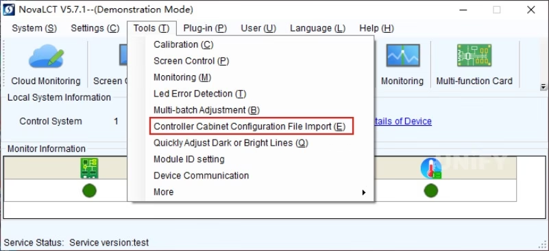
    (1) Log in and open the NovaLCT main interface, select “Tools” → “Controller Cabinet Configuration File Import.”

Figure 5-1 Software Function Entry Interface

(2) In the dialog box, click “Add Configuration File,” select the cabinet configuration file. After successful addition, the file name appears in the blank area. Click “Save Changes to Hardware” to import it into the controller. File name, deletion, and controller name can also be changed.

Figure 5-3 Sending Cabinet Configuration File

Send the configuration file from the controller to the cabinet receiving cards:
(1) On NovaStar V1160’s main menu, rotate the knob to select “Advanced Settings” → “Smart Configuration” → “Load Cabinet Configuration File.”
(2) Rotate the knob, select the imported file, press the knob, and the file is sent to all receiving cards.
(3) Save the configuration file into the receiving card.

Figure 5-3 Sending Cabinet Configuration File

Brightness Adjustment

After installation, the screen brightness is usually set at maximum. But in actual use, different customers and environments have different needs.

Therefore, brightness must be flexibly adjusted to ensure optimal visual experience. Taking NovaStar’s control system as an example:

1 Manual Adjustment
  1. Application Scenarios
    Commonly used when brightness needs to be adjusted on-site in real time.

  2. Operation Steps
    (1) Log in and open NovaLCT main interface, click “Brightness” to enter the dialog box.

Figure 5-4 “Brightness Adjustment” Dialog Box


Brightness Adjustment
coM99-Screen1
◎ Manual Adjustment      O Automatic Adjustment  Advanced

(2) Select “Manual Adjustment,” drag the slider or enter any value between 0–255. You can also observe the percentage in parentheses.
(3) In “Advanced Settings,” choose:

  • Gray Priority Mode: ensures grayscale effect, commonly for indoor screens.

  • Contrast Priority Mode: ensures contrast effect, commonly for outdoor screens.

2 Automatic Adjustment
  1. Application Scenarios
    Used when brightness must change with time or ambient light. Example: highway LED displays.

  • Daytime: strong sunlight → higher brightness.

  • Nighttime: lower brightness to avoid glare for drivers.

  1. Operation Steps
    (1) Log in and open NovaLCT, click “Brightness.”
    (2) Select “Automatic Adjustment,” then “Wizard Settings.” The wizard shows two modes: “Advanced Adjustment” and “Light Sensor Adjustment.”


Figure 5-5 “Wizard Settings – Type Selection” Interface

(3) Time Table Adjustment. With “Advanced Adjustment,” different brightness levels can be set for different time periods. For example, 08:00 set to 100%, 18:00 set to 10%.

Figure 5-6 “Automatic Adjustment Table” Interface

(4) Light Sensor Adjustment. By connecting an external light sensor, brightness is automatically adjusted based on ambient light. The “Light Sensor Configuration” dialog is shown below.

Figure 5-7 “Light Sensor Configuration” Dialog Box

Figure 5-8 NovaStar NS060 Light Sensor

Firmware Upgrade and Query

Firmware is a collection of control instructions. Without it, neither sending cards nor receiving cards can function.

Regular upgrades have benefits:

  • Fix known bugs, optimize features, improve stability.

  • Enable new functions.

  • Resolve inconsistent firmware issues causing display differences.

Firmware can be downloaded from the official website.

Figure 5-9 NovaStar Firmware Download Center

Steps:
(1) Log in and open NovaLCT, click blank, enter “admin,” “666888,” “123456.” The upgrade interface appears.

Figure 5-10 Upgrade Interface

(2) Click “Browse,” select the last subfolder of the unzipped firmware, then click “Update.”

Figure 5-11 Firmware Update Path Selection

(3) After success, click “Refresh” to confirm the firmware version matches the upgrade.

Figure 5-12 Confirm Upgrade Success

Pre-Stored Image

1 Application Scenarios

LED systems are complex with multiple devices and cables. Failures are common and hard to fix quickly. With “Pre-Stored Image,” if cables or signals are lost, the display still shows the pre-stored image instead of going black.

Some users also set posters or logos as startup images, reducing complexity.

2 How to Set Pre-Stored Image

(1) Log in and open NovaLCT, click “Settings” → “Pre-Stored Image.” Ensure normal connections and direct computer-controller link, with no third-party devices.

Figure 5-13 “Pre-Stored Image Settings” Dialog (1)

(2) Click “Browse” to select path.

Figure 5-14 “Pre-Stored Image Settings” Dialog (2)

(3) Choose “Full-Screen Effect” or “Single Cabinet Effect.”

Figure 5-15 Full-Screen Effect

Figure 5-16 Single-Cabinet Effect

(4) For full screen, you can select “Tile,” “Stretch,” or “Center.” Save to receiving card.

Figure 5-17 Full-Screen Effect Settings

(5) In “Function Settings,” you can set:

  • Startup Image: displayed when powered on.

  • Network Cable Disconnected or No Video Source: choose “Black Screen,” “Previous Frame,” or “Pre-Stored Image.”

Controller Front Panel Operation

Modern synchronous controllers are equipped with knobs and LCDs for simple front-panel operations. Example: NovaStar MCTRL660 PRO front panel.

Figure 5-18 NovaStar MCTRL660 PRO Front Panel

Knob functions are listed in Table 5-1.

Table 5-1

1 Input Settings
  1. Input Source Setting
    MCTRL660 PRO supports 3G-SDI, Single-Link DVI, and HDMI 1.4a. Select accordingly.

Figure 5-19 Input Source Setting Steps

  1. Input Resolution Setting
    Select preset resolution and refresh rate.

Figure 5-20 Input Resolution Setting

2 Quick Screen Connection

If connections are not set correctly, cabinets may display scrambled or repeated images. Quick screen connection solves this.

Figure 5-21 Screen Scrambling

Figure 5-22 Quick Screen Connection Steps

3 Image Control

Controls current screen state: Normal, Blackout, Freeze, Test Image.

Figure 5-23 Image Control Steps

4 Brightness Adjustment

Adjusts brightness via front panel for environment and comfort, prolonging LED lifespan.

Figure 5-24 Brightness Adjustment Steps

5 System Settings 5系统设置

Includes: 包括:

  • Factory Reset: restores default parameters.Factory Reset:恢复系统默认参数。

  • Return to Main Interface Time: 30–3600s.返回主界面时间:30 – 3600秒。

  • OLED Brightness Adjustment: range 6–15.OLED亮度调节:范围6-15。

  • Hardware Version: check version, upgrade with NovaLCT if new version available.硬件版本:检查版本,如果有新版本,使用NovaLCT升级。

Figure 5-25 System Settings Steps

Recommend Products

Contact Us

Order LED Screen? Please feel free to contact us at any time, and we will respond to you within 24 hours.