LED Display Configuration and System Debugging
- Home
- »
- LED Display Technology
- »
- LED Display Configuration and System Debugging
Table of Contents
LED Display Debugging Conditions and Software/Hardware Environment
1. LED Display Debugging Conditions and Inspection Items
(1) Debugging Conditions
- Review relevant technical documents, records, and construction drawings for the LED display ; coordinate the completion of electrical installation work.
- Installation quality must be verified to comply with design specifications, manufacturer’s technical documents, and construction acceptance standards.
- All relevant tests during installation must be completed and meet standards.
(2) Pre-Debugging Inspection Items
Communication and Power Line Inspection:
- After installation, inspect communication and power lines to ensure accurate communication and safe, reasonable power usage.
- Communication Line Inspection: Includes internal and external lines, ensuring normal signal transmission, clear labeling, and compliance with standards.
- Power Line Inspection: Covers cables from the display to the distribution box, lighting in maintenance channels, air conditioning, axial fans, and control room equipment wiring.
Module Inspection:
- Before debugging, ensure each module operates normally. Although modules undergo a 72-hour dynamic aging test at the factory, issues like loose connectors may occur during transportation or installation. Conduct a no-power inspection.
Auxiliary Equipment Inspection:
- Quantity Verification: Confirm that the model, quantity, and specifications of equipment match the contract (per delivery list). Verify the completeness of manuals, CDs, certificates, and warranty documents.
- Quality Inspection: Ensure packaging is intact, equipment functions properly, and operates normally after connection.
- Appearance Inspection: Confirm no visible scratches on the display frame, consistent pixel tube installation, and no loose components or cracked casings.
- Internal Equipment Inspection: Focus on checking screw tightness, connector conditions, and equipment integrity.
- Ventilation and Safety Inspection: Ensure ventilation meets safety standards and verify the functionality of air conditioning and temperature control systems.
Environmental Conditions:环境条件:
- Indoor LED Display: Operating temperature: 0°C to +40°C.
- Outdoor LED Display: Operating temperature: Optional -20°C or -10°C to +50°C.
- Humidity: Operates normally at 90% relative humidity at the maximum operating temperature.
- Leakage Current: Ground leakage current ≤3.5mA (AC RMS).
- Grounding Resistance: Outdoor display ≤4Ω, control room ≤1Ω.
2. LED Display Software and Hardware Environment
(1) Hardware Environment
The hardware for LED displays includes general-purpose computers, communication lines, data conversion components, and power supplies, customized based on display type, size, and site conditions. Detailed specifications include:
- Requirements for the computer host, optional cards, peripherals, and communication interfaces.
- Specifications for communication lines and maximum communication distance.
- Communication methods between data conversion components and the host.
- Power supply and structural installation requirements.
(2) Software Environment
Software for different LED displays must meet display function requirements and have the following features:
- Compliance with serialization, standardization, and backward compatibility.
- Use of specified operating systems and languages per standards.
- Inclusion of comprehensive self-diagnostic programs and tools as needed.
- Provision of dedicated software for displays with special purposes.
3. Common Graphics Card Settings
(1) ATI-AGP/PCI Series Graphics Card
- Right-click on the desktop and select Properties from the context menu.
- In the Display Properties dialog box, select the Settings tab, click Advanced, and then choose Display.
- In the FPD Display dialog box, click the red triangle button to turn it green, as shown in Figure 3-1, then click Apply.
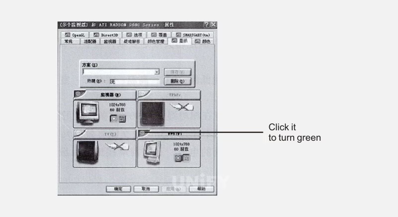
Figure 3-1: FPD Display Dialog
For video playback, select Overlay in advanced properties, click Clone Mode Options, choose Same on All, as shown in Figure 3-2, then click Apply.
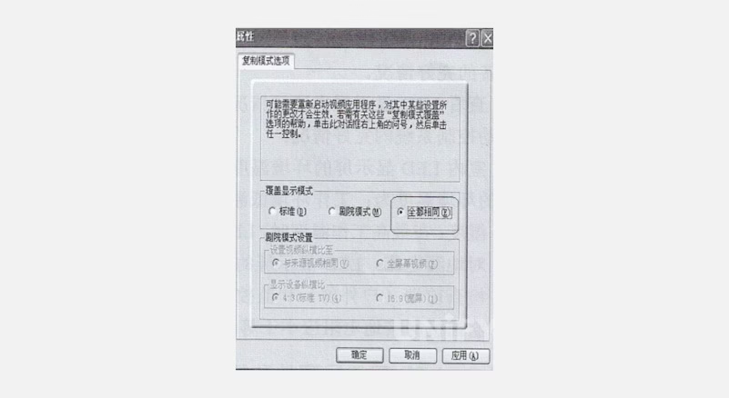
Figure 3-2: Advanced Properties Dialog
(2) ATI PCI-E graphics card
Right-click on the desktop and select “ATI CATALYST(R) Control Center” to open the “ATI Control Center”, as shown in Figure 3-3.
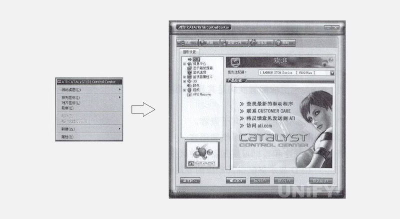
Figure 3-3: ATI Control Center Dialog Interface
In the right menu of the dialog, select Display Manager, as shown in Figure 3-4.
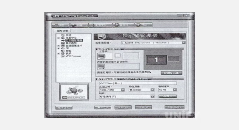
Figure 3-4: Display Manager Dialog
Right-click the grayed-out monitor under Connected Displays Currently Disabled, select Clone Main Digital Panel, as shown in Figure 3-5, confirm by selecting Yes to keep settings, as shown in Figure 3-6. Final setup is shown in Figure 3-7.
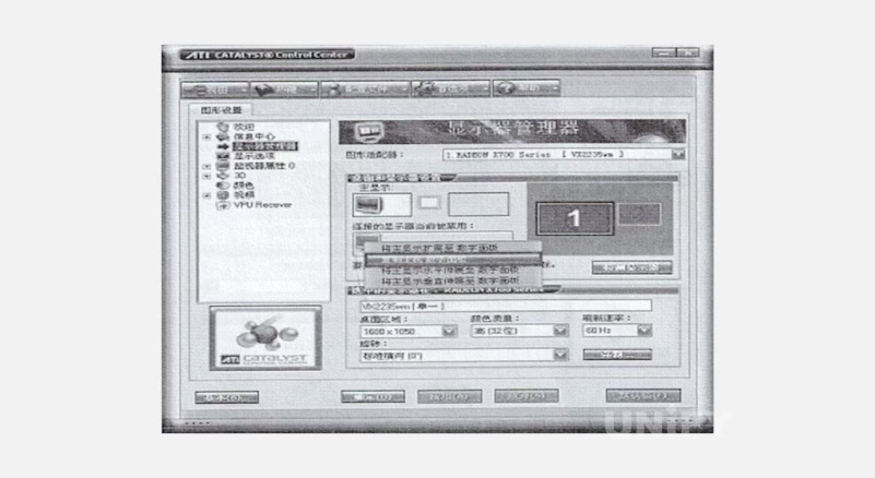
Figure 3-5: Clone Main Digital Panel Dialog
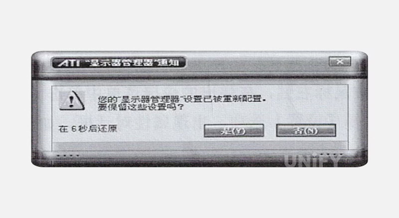
Figure 3-6: Confirm Settings Dialog
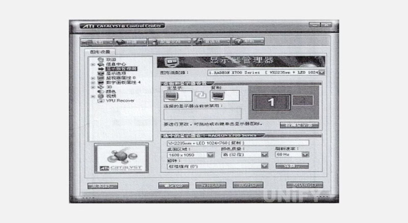
Figure 3-7: Final Setup Interface
To enable background playback, select “Extend Main Display to Digital Panel” as shown in Figure 3-8.
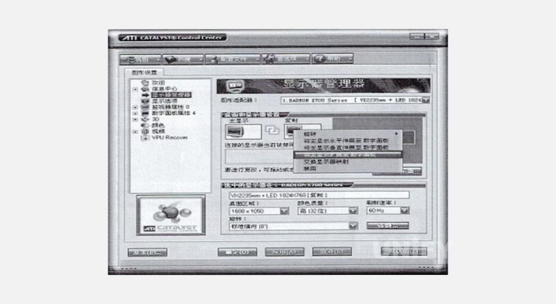
Figure 3-8: Extend Main Display to Digital Panel Dialog
(3) Rooftop Style. LED displays installed in city squares often use the rooftop installation method, mounted on the roofs of surrounding buildings. The rooftop installation diagram is shown in Figure 2-8
For video playback, select Video, choose Theater Mode, and under Clone Mode Display Overlay, select Same on All Displays, as shown in Figure 3-9, then click Apply.
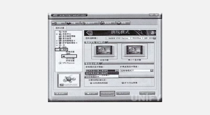
Figure 3-9: Same on All Displays Dialog
(3) NVIDIA Series Graphics Card
Right-click on the desktop, select Properties, then choose Settings in the Display Properties dialog, as shown in Figure 3-10.
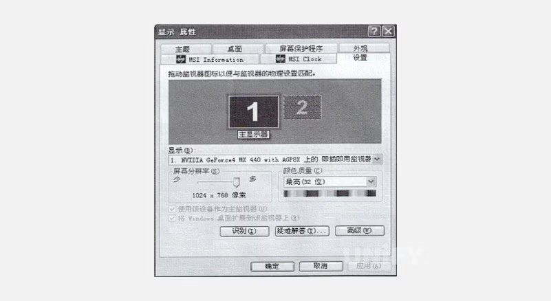
Figure 3-10: Properties Dialog
Click Settings, then Advanced to open the advanced dialog, as shown in Figure 3-11.
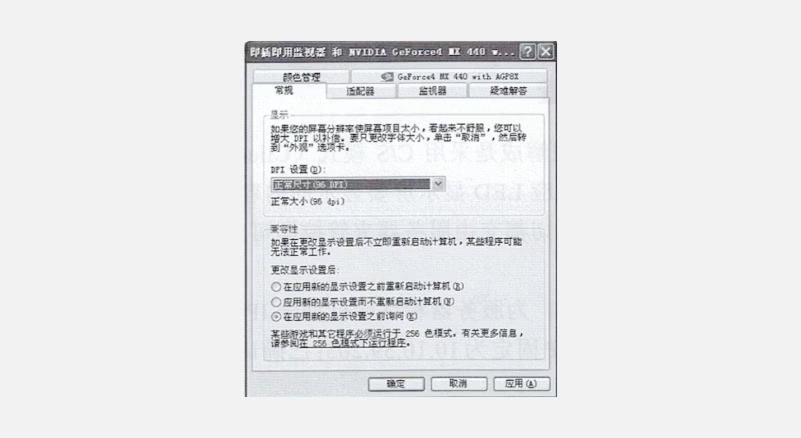
Figure 3-11: Advanced Dialog
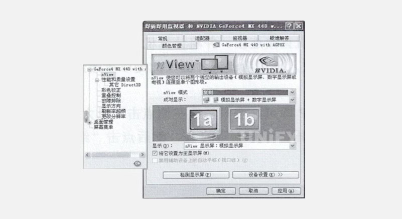
Click GeForce4…, select nView from the left menu, as shown in Figure 3-12.
Figure 3-12:nView Dialog Box
In nView mode, select Clone, then click Apply. For video playback, select Troubleshooting or Performance in advanced properties, as shown in Figure 3-13.
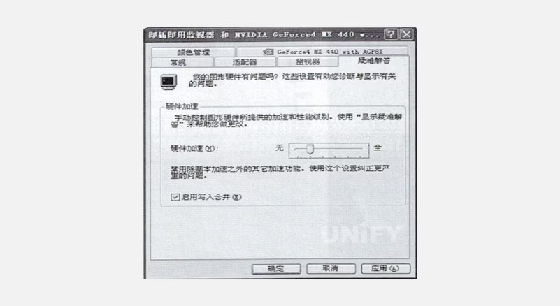
Figure 3-13: Troubleshooting or Performance Dialog
Set hardware acceleration to basic or none, then click Apply.
LED Display Configuration and Sending/Receiving Card Settings
1. LED Display Configuration
LED display applications operate in a Client/Server (C/S) mode, with servers controlling content design. Terminals connect to the server for operation, managed entirely by the server.
(1) Pre-Preparation
Plan the network, assigning IPs (e.g., terminal IPs: 10.10.59.201–204, server IP: 10.10.59.205). Confirm terminal login credentials (username: admin, password: 123456).
(2) Configuration Steps
IP Configuration: For initial terminal IP changes, connect the computer to the terminal’s switch or directly to the terminal. Set computer IP to 192.168.0.x. Enter the terminal IP in the address bar, log in with correct credentials. Set Ethernet IP by disabling DHCP, assigning a fixed IP, and clicking Terminal Restart, as shown in Figure 3-14.
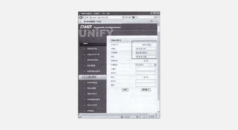
Figure 3-14: Ethernet IP Configuration Interface
Server Configuration: Set server IP (10.10.59.205), port (60001), and terminal ID (BOX0000x, unique, with 5-digit suffix). Port must be 60001. Save settings by clicking Modify, as shown in Figure 3-15. Check terminal and server configuration via Terminal Network Status View, as shown in Figure 3-16. Restart terminal to apply changes.
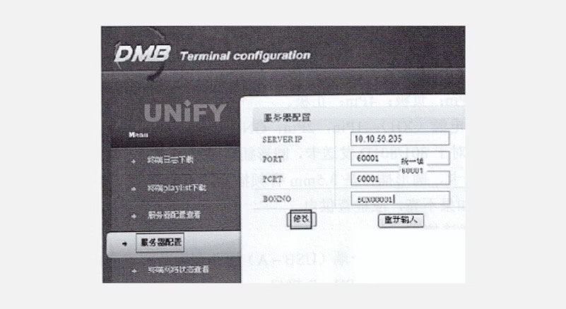
Figure 3-15: Server Configuration Interface
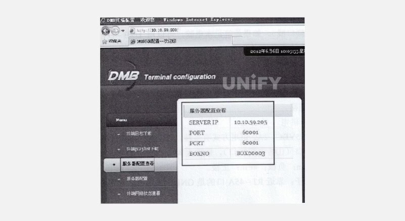
Figure 3-16: Configuration Viewing Interface
After configuration, design content on the server, click Apply to display on the terminal in real-time.
2. Linsn Control System Sending/Receiving Card (9th Gen) Settings
(1) Sending and Receiving Card Connections
Sending Card Connection:
Step 1: Power Supply: Specs: 5–6.3VDC, 2A. Options:
PCI slot (desktop, power only, no data).
D-shaped power (IDE, big 4-pin): 1Pin: N/C, 2/3Pin: Negative, 4Pin: Positive.
Bar connector (XH): 1/2Pin: GND, 3/4Pin: Positive.
Round socket: For 801/801D, long pin is positive; for 802/802D, 3.5mm audio, no power. Red LED indicates normal power.
Step 2: Communication Line: Connect USB-A to the computer (with or to install LED Studio), USB-B to sending card.
Step 3: Data Line: Connect DVI signal source to sending card DVI-D (compatible with DVI-A). Use USB-DVI or HDMI-DVI for laptops.
Step 4: Enable Data Communication: Green LED flashing indicates normal communication. If off, enable graphics card clone mode.
Receiving Card Connection:
Step 1: Power Supply: Specs: 3.3–5VDC, 2A. Options:
D-shaped power (IDE, big 4-pin): 1Pin: N/C, 2/3Pin: Negative, 4Pin: Positive.
Power terminal: GND near RJ-45A. Red LED indicates normal power.
Step 2: Signal Reception: Two RJ-45 ports (A/B, interchangeable). Connect sending card RJ-45 to receiving card RJ-45. Green LED flashes (faster on A, slower on B) for normal data. For multiple cards, cascade with network cables. If no flash, check cable connections, consistency (T568A or T568B), and integrity.
Step 3: Module/Cabinet Connection: Use manufacturer-provided adapter boards or match module interface. Connect via 50-pin ribbon cable if needed. Follow manufacturer instructions for RCG and CON files.
(2) Sending Card Settings
Click Software Settings in the menu, enter “linsn” (lowercase, re-enter if incorrect), then password 168 to access the sending card settings dialog, as shown in Figure 3-17.
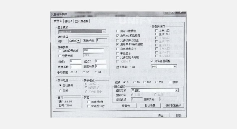
Figure 3-17: Sending Card Settings Dialog
Settings overview:
Display Mode: Set to match computer monitor/signal source resolution (e.g., 1024×768 default). Adjust if needed, save to sending card, disable graphics card clone, set matching resolution, then re-enable clone.
Port: USB-bridged COM port, auto-detected (COM1–COM6). Manually adjust in Device Manager if beyond COM6.
Sending Card Count: Number of connected sending cards.
Auto Set Starting Point: Adjusts sending card height Y starting point (e.g., 120 in Figure 3-17).
Set Width: Set load width (≥ screen width). Single network cable load height ≤ display mode height, total points = 655360 (height = 655360 ÷ screen width).
Starting Point X/Y: Set screen area starting point, within sending card load range. Set via Set Large Screen Area menu.
Width/Height Coefficient: Scale content (actual width/height ÷ target width/height).
Manual Grayscale: Set brightness levels (16, 32, or 64).
Screen Power:
Auto-switch: Outputs signal with DVI input.
Off: Stops signal output, linked to Enable/Disable Large Screen Power menu.
Async Mode: Reserved.
Hardware: Sending card program version and model.
Other: 32-point fold 8/16 rows for special screens (generally unused).
Enable 10-Bit Color: For external digital interfaces.
Enable DVI Plug-and-Play: Auto-activates DVI port.
Allow Software Point Correction: Enables correction, disable to revert.
Enable Card/Cabinet Monitoring: Activates monitoring in Settings menu (reserved).
Enable Single-Point Monitoring: Reserved.
Monochrome Display: Displays single color (full-color black/white).
Allow Function Card Brightness: Enables auto-brightness adjustment.
Remember Network Card: For gigabit network cards.
Graphics Card Frequency: Current frequency.
Hot Backup Port: For intelligent connections.
Allow Color Temperature Adjustment: Enables color temperature settings (default recommended).
Rotation: Screen rotation via sending card.
Pixel Extraction Virtual: For staggered pixel boards.
Virtual Mode/Direction/Starting Point/Step: Pixel extraction settings.
Check Card: Verifies sending card model.
Default Settings: Restores factory settings.
Save to Sending Card/Exit/Help: Save, exit, or access help.
(3) Receiving Card Settings
Understanding the receiving card settings interface is crucial for efficient control system operation, as shown in Figure 3-18.
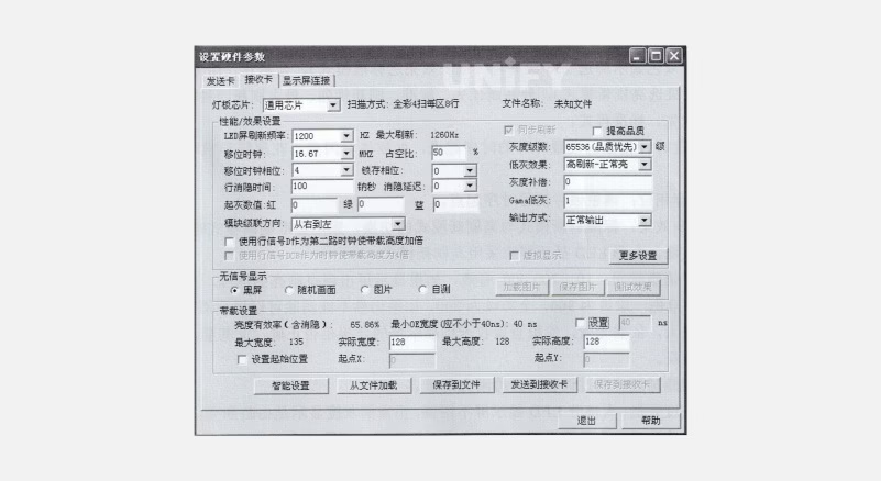
Figure 3-18: Receiving Card Settings Dialog
Settings overview:
Lamp Board Chip: LED driver chip. Scanning mode displays after intelligent settings or loading correct RCG file.
File Name: RCG file name (e.g., universal full-color 8-scan 8-row 8-fold).
Performance/Effect Settings:
Refresh Rate: Higher rates stabilize images (≥1000Hz for camera, 60–75Hz for dual-color).
Sync Refresh: Syncs with computer refresh rate (mandatory for full-color).
Improve Quality: Enhances low-gray effect in high-refresh mode, reduces brightness efficiency.
Shift Clock: Higher clock increases load area or supports higher grayscale/refresh (default 16.67MHz).
Duty Cycle: Adjusts shift clock duty cycle (default 50%).
Grayscale Levels: 256 for dual-color, 65536 for full-color. Modes: quality priority, standard, refresh priority, max refresh.
Shift Clock Phase: Adjusts timing for flash or garbled display.
Latch Phase: Adjusts latch signal timing.
Low Gray Effect: Switches between standard/high refresh modes.
Row Blank Time: Eliminates dim/bright issues (300 for dual-color, 200 for full-color).
Blank Delay: Improves dim/bright issues.
Grayscale Compensation: Adjusts uneven grayscale (0–15), as shown in Figure 3-19.

Figure 3-19: Normal Grayscale Diagram
Starting Grayscale Value: Manually adjusts RGB grayscale values.
Gamma Low Grayscale: Adjusts low grayscale via Gamma table.
Use Row Signal D as Second Clock: Doubles load height.
Module Cascade Direction: Rotates display without redoing intelligent settings.
Output Mode: Normal or 2–8 split outputs for higher refresh rates (e.g., right-to-left cascade):
Normal Output: 1–16 data groups top-to-bottom, width must be a multiple of 8.
Two-Split Output: 1–8 groups for left half, 9–16 for right half.
Three-Split Output: 1–5, 6–10, 11–15 groups split into three parts.
Four-Split Output: 1–4, 5–8, 9–12, 13–16 groups split into four parts.
Five-Split Output: 1–3, 4–6, 7–9, 10–12, 13–15 groups split into five parts.
Six-Split Output: 1–2, 3–4, 5–6, 7–8, 9–10, 11–12 groups split into six parts.
Seven-Split Output: 1–2, 3–4, 5–6, 7–8, 9–10, 11–12, 13–14 groups split into seven parts.
Eight-Split Output: 1–2, 3–4, 5–6, 7–8, 9–10, 11–12, 13–14, 15–16 groups split into eight parts.
Use Row Signal DCB as Clock: Quadruples load height.
Virtual Display: Enable for virtual screens and select “full-color virtual screen.”
More Settings:
Sequence 1–16: Default 16-group data output order.
Output Order: Manually swap any two data groups.
Starting Point: Sets data starting position (for irregular screens).
Dedicated Chip: Settings for chips like 1xy28161 (temperature protection, output delay) or MBI5042 (RGB current gain, PWM clock).
Output Port Odd-Even Swap: Swaps odd and even groups (e.g., 1 with 2, 3 with 4).
Output Port Reverse: Reverses 1–16 to 16–1.
Brightness Compatibility with Old Cards: For RV801D (high refresh) and older cards.
Type 2 Card 4 Output Ports: RV802D 26P interface converts 16 serial groups to 4 RGB parallel groups.
50-Pin Swap: Swaps 1–8 and 9–16 data groups.
Insert Blank Clock Before Data: For chips requiring clock insertion.
Type 2 Card 5 Output Ports: RV802D 26P converts 16 serial groups to 5 RGB parallel groups.
Two-Port Swap: Reorders 16 groups to 1, 9, 2, 10, etc.
20 Data Ports: Expands to 20 groups, requiring adapter board changes.
No-Signal Display: Options include black screen, last frame, picture (128×128, 16K colors), or self-test (horizontal/vertical lines, full bright, RGB).
Load Settings:
Brightness Efficiency (Including Blanking): Current brightness efficiency percentage.
Minimum OE Width: Not less than 40ns (for universal chips), for low grayscale issues or insufficient OE width.
Maximum Width: Maximum width per receiving card, tied to refresh rate, grayscale, and scan clock.
Actual Width: Actual loaded width per receiving card.
Maximum Height: Maximum height per receiving card, tied to driver board design.
Actual Height: Actual loaded height per receiving card.
Set Starting Position: Default (0,0) at the top-left corner. X/Y sets width/height starting points, within the sending card’s control range.
Intelligent Settings:
Seven steps (some may be skipped based on the driver board) to auto-detect driver mode and signal direction. Correct completion ensures normal module operation.
Align graphics card resolution with sending card display mode, set to clone mode, and ensure sending/receiving card green lights flash. Connect one module to the first data port of the adapter board (for full-screen settings, observe the first module). Follow dialog box prompts while observing module changes.
Load from File: Loads RCG file.
Save to File: Saves driver mode and signal direction as an RCG file after debugging, for reuse in identical modules.
Send to Receiving Card: After intelligent settings or loading RCG, click to apply modified settings.
Save to Receiving Card: Permanently saves data to the receiving card.
(4) Intelligent Setting Steps
Intelligent Setting Wizard 1:
Click intelligent settings; the LED screen/module lights up, entering Wizard 1, as shown in Figure 3-20.
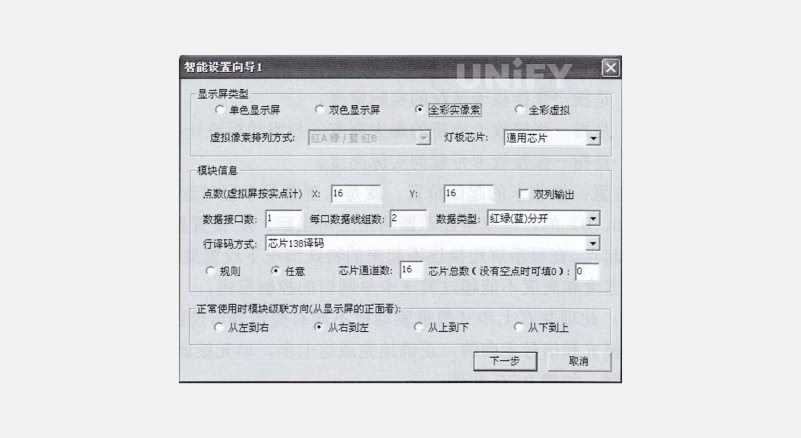
Figure 3-20: Intelligent Setting Wizard 1 Dialog Box
Select display type and LED board chip. For full-color virtual screens, choose the correct virtual pixel arrangement (e.g., two red, one green, one blue; upper row red as Red A, lower row as Red B), as shown in Figure 3-21.
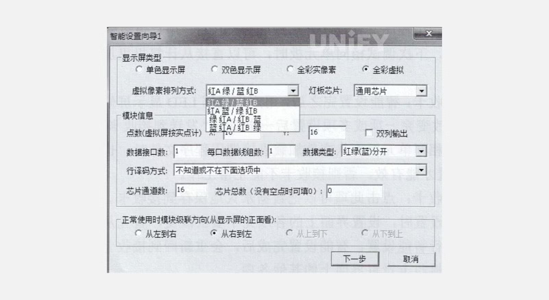
Figure 3-21: Virtual Pixel Arrangement Selection Dialog Box
Check the LED driver chip; for MBI5024, 74HC595, or similar, select universal chip; for PWM chips (e.g., MBI5041), select corresponding option (e.g., MBI5042), as shown in Figure 3-22.
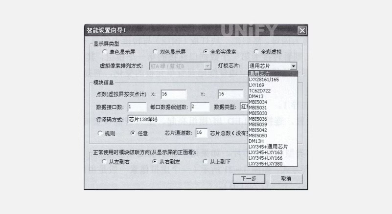
Figure 3-22: LED Board Chip Selection Dialog Box
Enter module information:
Points: Module pixel resolution (virtual screens use real points), X (width points), Y (height points), as shown in Figure 3-22.
Data Interface Count: Number of ribbon cable input ports (e.g., one input/output is 1), as shown in Figure 3-22.
Data Line Groups per Port: Number of RG or RGB data groups per ribbon cable interface.
Data Type:
If R, G, B DATA signals exist (red, green, blue chips separate), select “Red/Green/Blue Separate” for LED graphic displays.
If only one DATA or R signal (except monochrome, with red/green/blue chips in series), select “Red/Green/Blue Combined Serial” or “Four-Point Serial” for decorative or curtain screens.
HUB48 extended 3/4-color serial, HUB52 extended red/green/blue separate for guardrail tubes and point light sources, as shown in Figure 3-23.
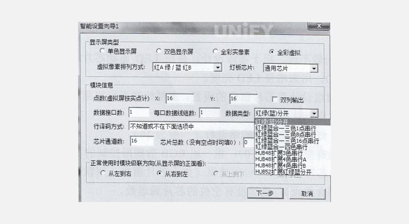
Figure 3-23: Data Type Selection Dialog Box
- Data type options:
Red/Green/Blue Combined 3-Color 1-Point Serial: Each three channels output R, G, B signals.
Red/Green/Blue Combined 3-Color 8-Point Serial: Each eight channels output R, G, B signals.
Red/Green/Blue Combined 3-Color 16-Point Serial: Each 16 channels output R, G, B signals.
Row Decoding Method: Check for 4953 row tubes (8-pin chips). If absent, select “Static No Decoding”; if present, check for 74HC138 or similar decoding chips, select “Direct Drive Row Tube with/without OE” or “Chip 138 Decoding,” as shown in Figure 3-24.
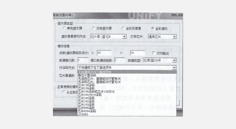
Figure 3-24: Row Decoding Options Dialog Box
1.Dual-Column Output: Generally not selected, used for special designs to enhance LED brightness.
Arbitrary: For modules with chip pin omissions (default if no omissions).
Chip Channel Count: Driver chip channel count (typically 16).
Total Chips: Number of driver chips controlled by one RGB data group (0 if no omissions).
Consecutive Points: Number of consecutive non-omitted chip channels.
Omitted Points: Number of consecutively omitted chip channels.
Module Cascade Direction: Data flow direction from the front of the display.
Intelligent Setting Wizard 2:
Display change options include “Auto Change” and 1, 2 options. If selecting 1 or 2, deselect “Auto Change,” observe module changes, and select the correct display state (e.g., 1 for white, 2 for black), as shown in Figure 3-25.
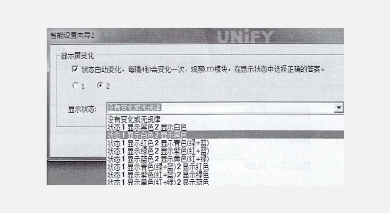
Figure 3-25: Intelligent Setting Wizard 2 Dialog Box rotection
Intelligent Setting Wizard 3:
Observe the module and select the correct display state (deselect “Auto Change” for manual 1, 2 selection), as shown in Figure 3-26.
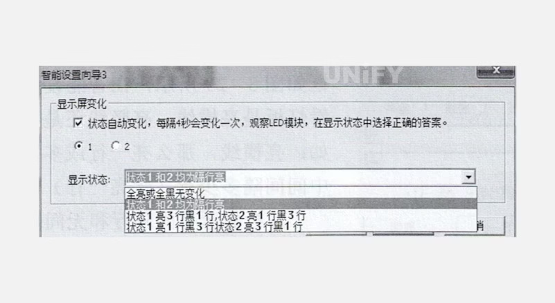
Figure 3-26: Intelligent Setting Wizard 3 Dialog Box
Intelligent Setting Wizard 4:
Observe module states 1 and 2, compare brightness (e.g., if 1 is brighter than 2, select state 1 brighter, deselect “Auto Change”), as shown in Figure 3-27.
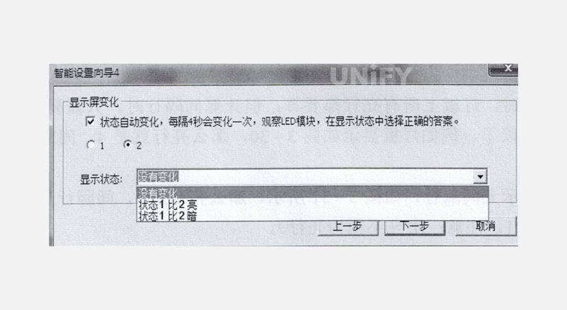
Figure 3-27: Intelligent Setting Wizard 4 Dialog Box
Intelligent Setting Wizard 5:
Observe module colors in respective state options (e.g., red for state 1, green for state 2, blue for state 3, black for state 4, deselect “Auto Change”), as shown in Figure 3-28.
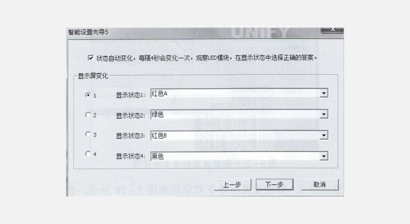
Figure 3-28: Intelligent Setting Wizard 5 Dialog Box
Intelligent Setting Wizard 6:
Observe module for lit horizontal, vertical, or both lines, and select the correct state. Count all lit rows for bright rows; count rows between two lit rows for spacing (e.g., Figure 3-30: 4 bright rows, 2 spacing rows; Figure 3-31: 4 bright rows, 1 spacing row), as shown in Figure 3-29.
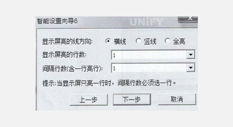
Figure 3-29: Intelligent Setting Wizard 6 Dialog Box
Figure 3-30: Module Display with31: Spaced Rows

Figure 31- Module Display without Spaced Rows
Intelligent Setting Wizard 7:
Each grid represents a pixel. Observe the module’s lit point, click the corresponding grid, and continue as prompted until complete, as shown in Figure 3-32. Supports back (for errors) and reset (to restart).
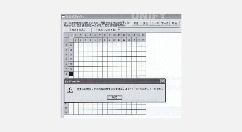
Figure 3-32: Module Display Observation Dialog Box
(5)Notes on Modules with Arbitrary Chip Omissions
Intelligent Setting Wizard 1 X and Y: Calculate based on non-omitted pixel points (e.g., module width 36 points, height 16 points, set X=48, Y=16).
Arbitrary Option: Select “Arbitrary” in Wizard 1.
Wizard 7: If no bright points appear, click grids after the actual width until a bright point appears, then click the corresponding grid.
Manual Settings: After intelligent settings, enter “manual” in the receiving card scan file interface to access the “Manual Settings” list and modify:
VerySkipDot: Actual width – 1 (e.g., 36-1=35).
SkipDot: Omitted points per row + 1 (e.g., 12+1=13).
WidthExt: Change 0 to 1.
MSkipDot: Change 0 to 1.
Confirm and Set Width: Set the actual width in the receiving card interface to the desired width and send, as shown in Figure 3-33.
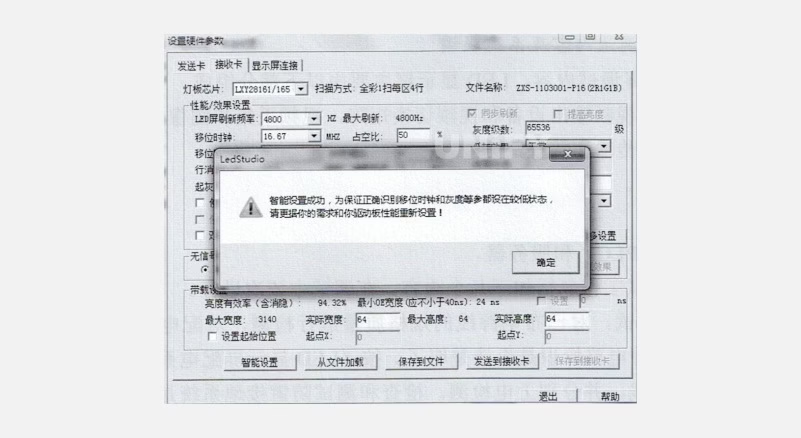
Figure 3-33: Hardware Parameter Settings Dialog Box
Complete Settings: Set refresh rate and grayscale as needed to finalize receiving card settings.
LED Display System Debugging and Playback Software Application
1. LED Display System Debugging
(1) Debugging Plan Compilation Standards
Refer to Table 3-1 for standards.
Table 3-1: LED Display Debugging Plan Compilation Standards
Standard No. | Standard Name |
|---|---|
SJ/T 11141 | General Specification for LED Displays |
GB 2421 | Basic Environmental Testing Rules for Electrical and Electronic Products |
GB 2421 | Terminology for Basic Environmental Testing Rules |
GB 2423.1 | Low-Temperature Test Rules |
GB 2423.2 | High-Temperature Test Rules |
GB8898—1988 | Safety Requirements for Household Electronic Equipment |
GB 50054—1995 | Low-Voltage Distribution Design Code |
GBJ232—1982 | Electrical Installation Construction and Acceptance Code |
GB9366—1988 | Computer Site Safety Requirements |
FVJ 65—1988 | Grounding Design Code for Industrial and Civil Power Systems |
GBJ 79—1985 | Industrial Communication Grounding Design Code |
SDJ 8—1998 | Technical Code for Power Equipment Grounding Design |
(2) Debugging Content and System Integration
Debugging Content:
Video components (output devices, switching matrix, acquisition, and processing units).
Signal transmission (sending, transmission, receiving).
LED display.
Power distribution system.
Industrial control equipment (PLC) and servers.
Debugging Steps:
Power Distribution: Verify power line specifications, test distribution cabinet connections, check circuit labels, connect per design diagrams, test individually, and verify lightning grounding.
PLC System: Debug after power distribution, including:
Verify control line connections, module installation, software setup.
Test manual/auto operation, temperature/smoke monitoring, fire alarms, brightness adjustment.
Control System:
Verify signal transmission from computer to video matrix/multimedia system.
Check multimedia to controller, controller to fiber transmitter, fiber transmitter to receiver, receiver to cabinet.
Application Software:
Platforms: Single-machine (WinXP/Vista), network (WinNT).
Playback software: General display, operational, video playback.
Control software: LED control panel, LECADJ, PLC.
Debug playback software during single-screen tests, specialized software with user cooperation, control software during system integration.
Unit Display Cabinet:
Pre-power checks, power-on tests, ensure normal operation.
Verify temperature control and fan functionality.
Self-Test and Testing/Validation/Adjustment:
Self-test control diagram, as shown in Figure 3-34.
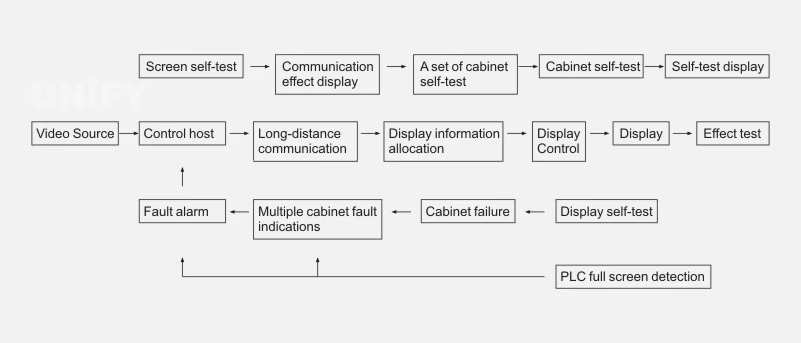
Figure 3-34: LED Display Self-Test System Control Diagram
Testing/validation/adjustment diagram, as shown in Figure 3-35.
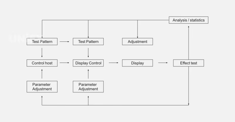
Figure 3-35: LED Display Testing, Validation, Adjustment System Control Diagram
Test full-screen characteristics, brightness uniformity, pixel properties, grayscale balance.
Validate brightness accuracy, grayscale offset, color space, low-gray effect, reflections, refresh rate, color temperature, module structure, LED arrangement.
Brightness and Nonlinear Correction:
Adjust brightness and nonlinearity using dedicated software for 1024-level grayscale.
Control brightness, apply nonlinear correction (8 curves per color), adjust offsets.
Color Measurement:
Use imaging colorimeter (PM-1400) for luminance and chromaticity measurement.
Requires CIE-compliant filters, 12-bit dynamic range, low noise, full-frame CCD.
Screen Calibration:
Measure each LED’s luminance/chromaticity, calculate 3×3 correction matrix.
Map outputs to NTSC/HDTV color spaces, calibrate on-site at night for outdoor screens.
(3) System Integration
Conduct after PLC, power, network, and software systems are operational. Ensure compatibility with TV broadcasts and other studios, supporting various video/audio/computer signal inputs.
Debug single screens in the control room, testing text, graphics, animations, and videos. Cabinets with relays enable/disable display circuits for energy efficiency.
Signal flow supports flexible allocation with reliable emergency systems. Process involves video switching, PCI signal processing, LVTTL signal driving, frame control, fiber transmission, and display module cascading.
Image Input:
Analog: Graphic (DB-15), HDTV (YPbPr).
Video: Four analog inputs (Tuner, S-terminal, two composite).
DVI: PCI graphics output.
Image Processing:
Digital brightness/chroma enhancement.
Programmable brightness/contrast/saturation.
Motion compensation, de-interlacing, noise reduction.
Film mode detection, progressive scanning, pixel-level compensation.
Normalized scaling for 4:3 and 16:9 modes.
Image Output: Resolution 640×480 to 1920×1080, supports large images on small screens. Factory debugging includes 72-hour module tests and system integration. Troubleshoot by verifying computer operation, restarting software/computer, checking power, and communication lines.
(4) Network System Debugging
LAN debugging (control computers, servers, hubs).
Internet debugging: Each cabinet has four network ports (one input, three outputs). Supports audio/video/control signal transmission, remote power control, and network information playback.
2. LED Display Playback Software Application
Run LED Studio software by double-clicking the desktop shortcut.
(1) Program Composition
Programs consist of one or more pages:
Normal Pages: Multiple, played sequentially.
Global Page: One, plays continuously (e.g., clocks, logos). Pages contain one or more windows (12 types):
File Window: Plays text, images, animations, tables.
Text Window: Quick input for short texts (e.g., notices).
Single-Line Text Window: Single-line text (e.g., ads).
Static Text Window: Fixed text (e.g., company names).
Table Window: Edits/plays table data.
Timer Window: Supports forward/reverse timing.
Database Window: Plays ACCESS/ODBC databases.
DVD/VCD Window: Plays DVD/VCD.
External Program Window: Embeds user-developed programs.
Date-Time Window: Displays date/time.
Video Input Window: Plays TV/video capture signals.
Geometric Figure Window: Displays lines/circles (currently unavailable).
(2) Program Creation Process
Set Playback Window Size: Ensure correct size to avoid partial display. In Settings > Software Settings > Playback Window, lock to LED display size, or set multi-screen, sync, or arbitrary position. For arbitrary, set screen count to 1, click Update Screen Count, set starting point (0,0), and width/height (e.g., 192×96 for 128×92 screen), as shown in Figure 3-36.
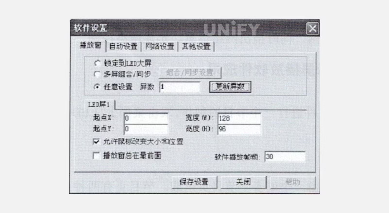
Figure 3-36: Playback Window Interface
Create Program Page: Click New Program Page in the program toolbar, as shown in Figure 3-37. Delete pages with Delete, reorder with Move. Normal pages play sequentially; global pages play continuously.
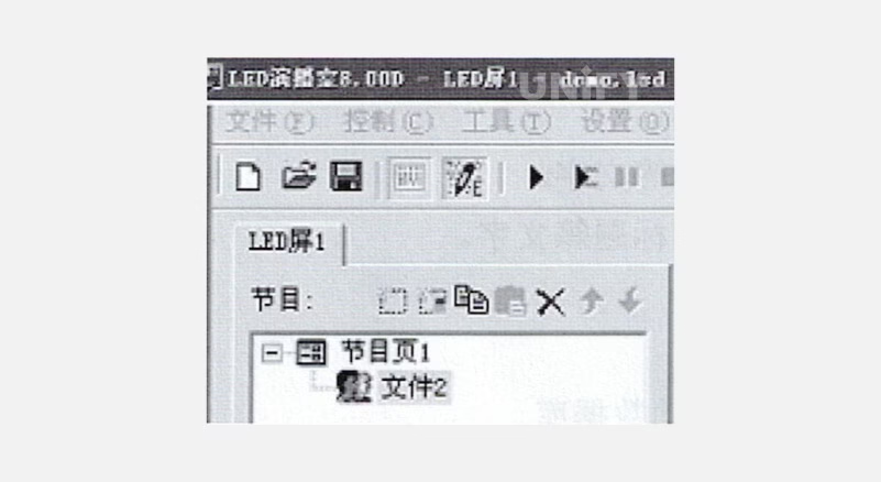
Figure 3-37: Program Toolbar
Set Program Page Options: Configure name, playback time, background color/image, drawing method, and music, as shown in Figure 3-38.
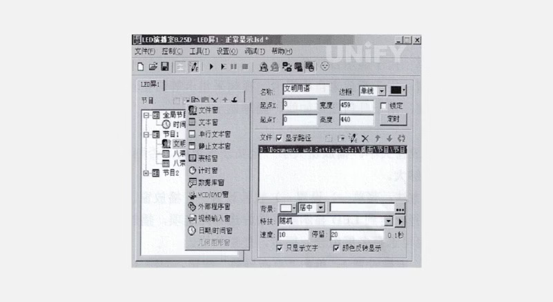
Figure 3-38: Program Page Options Dialog
Create Program Window: Add windows (12 types) via New Program button, as shown in Figure 3-39.
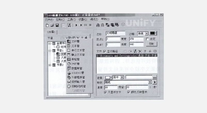
Figure 3-39: Program Selection Menu
File Window: Supports text, web, Excel, Word, images, media, VCD, Flash, RealPlay files.
Text/Single-Line/Static Text Windows: Quick text input.
Table, Timer, Database, DVD/VCD, External Program, Date-Time, Video Input, Geometric Figure Windows: As described.
Set Program Window Options: Configure name, border, color, position, size, locking, timing, as shown in Figure 3-40
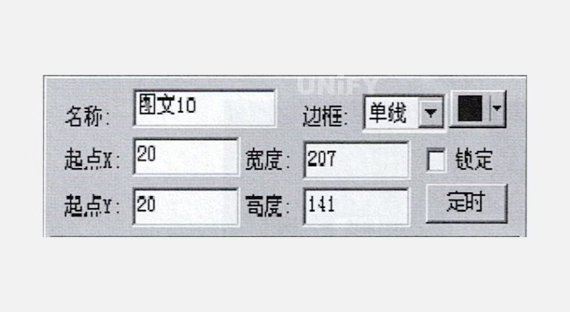
Figure 3-40: Program Options Window
File Window: Supports text, web, Excel, Word, images, media, VCD, Flash, RealPlay files.
Text/Single-Line/Static Text Windows: Quick text input.
Table, Timer, Database, DVD/VCD, External Program, Date-Time, Video Input, Geometric Figure Windows: As described.
Set Program Window Options: Configure name, border, color, position, size, locking, timing, as shown in Figure 3-40.
File Window: Lists files above, options below (text/image-specific), as shown in Figure 3-41.
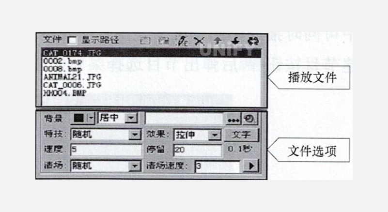
Figure 3-41: File Window
Text File Options: Background, effects, font, as shown in Figure 3-42.
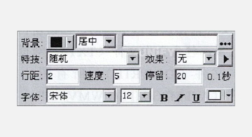
Figure 3-42: Text File Options Window
Image File Options: Supports all formats, effects, clear settings, as shown in Figure 3-43.
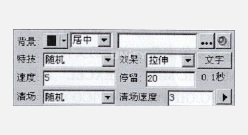
Figure 3-43: Image File Options Window
Video Input Window: Options tied to video input devices, as shown in Figure 3-44.
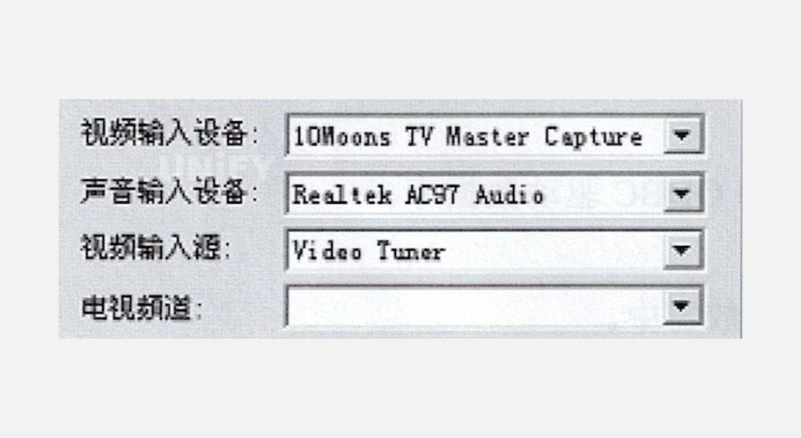
Figure 3-44: Video Input Window
Complete Program: Repeat steps 2–5 for multiple pages. Save via Save button or File > Save.
Play Program: Click Play to start, Pause, Stop, or open another file via Open, then play.
Recommend Products

Digital Signage Saudi Arabia Solutions for NEOM and Vision 2030
Discover advanced Digital Signage Saudi Arabia solutions for smart cities. Elevate your mega-projects with our eco-friendly, heat-resistant LED displays.

Ultimate Guide: Rental LED Screen Supplier Saudi Arabia | UnifyLED
Need a reliable rental LED screen supplier in Saudi Arabia? Elevate your Riyadh Season events with UnifyLED’s weather-proof, fast-setup GOB LED screens.

Stadium LED Screen Saudi: Tech Solutions for the 2034 World Cup
Upgrade your venue with the leading Stadium LED screen Saudi technology for the 2034 World Cup. UNIFYLED offer FIFA-standard perimeter displays, extreme heat resilience, and end-to-end installation support.